Lexmark 2050 Color Jetprinter Service Manual - Page 45
Maintenance Station Assembly Removal, Maintenance Wipers and Caps Removal, Manual Insert Tray Removal
 |
View all Lexmark 2050 Color Jetprinter manuals
Add to My Manuals
Save this manual to your list of manuals |
Page 45 highlights
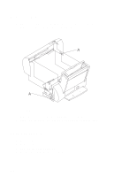
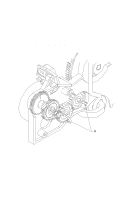
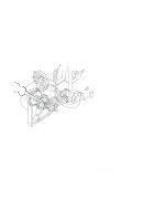
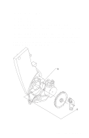
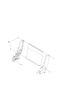
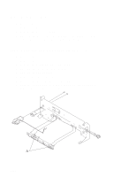
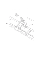
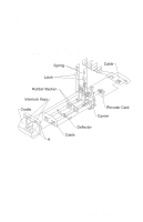
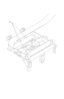
Maintenance Station Assembly Removal 1. Remove the front cover. 2. Remove the rear cover. 3. Remove the screw from the maintenance station assembly, lift up the right side of the mid frame assembly and slide the maintenance station assembly forward, out of the printer. Maintenance Wipers and Caps Removal 1. Remove the front cover. 2. Push the carrier to the left away from the maintenance station. 3. Gently pull the caps and wipers off their mountings. Note: When reinstalling the caps, be sure the cap is positioned with the locking tabs to the left and right before pushing them down on their mounting posts. Be sure the wipers are completely seated. Manual Insert Tray Removal 1. Remove the front cover. 2. Remove the rear cover. 3. Remove the paper load door. 4. Spread the right side frame away from the manual insert tray until the pins in the insert tray clear the frame. 5. Remove the manual insert tray from the left side frame. Mid Frame Assembly Removal 1. Remove the front cover. 2. Remove the rear cover. 3. Remove the carrier frame assembly. 4. Remove the paper load door and manual insert tray. 5. Remove the small feed roll shaft. 6. Unlatch the left side of the exit roller shaft and work the belt off the exit roller pulley. 7. Pull up the four clips securing the mid frame to the large feed roll and work the mid frame out of both side frames. Repair Information 4-13
-
 1
1 -
2
-
3
-
4
-
5
-
6
-
7
-
8
-
9
-
10
-
11
-
12
-
13
-
14
-
15
-
16
-
17
-
18
-
19
-
20
-
21
-
22
-
23
-
24
-
25
-
26
-
27
-
28
-
29
-
30
-
31
-
32
-
33
-
34
-
35
-
36
-
37
-
38
-
39
-
 40
40 -
 41
41 -
 42
42 -
 43
43 -
 44
44 -
 45
45 -
 46
46 -
 47
47 -
 48
48 -
 49
49 -
 50
50 -
51
-
52
-
53
-
54
-
55
-
56
-
57
-
58
-
59
-
60
-
61
-
62
-
63
-
64
-
65
-
66
-
67
-
68
-
69
-
70
-
71
-
72
-
73
-
74
-
75
-
76
-
77
-
78
-
79
-
80
-
81
-
82
-
83
-
84
 |
 |
