Lexmark 2050 Color Jetprinter Service Manual - Page 51
Printhead Carrier Assembly Removal, Printhead Rubber Backer Removal, Repair Information 4-19
 |
View all Lexmark 2050 Color Jetprinter manuals
Add to My Manuals
Save this manual to your list of manuals |
Page 51 highlights
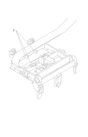
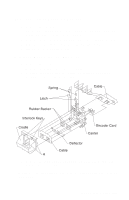
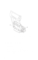
Printhead Carrier Assembly Removal 1. Remove the front cover. 2. Unlock the four printhead cable connectors and disconnect the printhead cable from the system board. 3. Remove the retainer from the right end of the carrier guide rod. 4. Slide the carrier guide rod to the left, out of the printer. 5. Lift the carrier out of the printer. Printhead Rubber Backer Removal 1. Remove the front cover. 2. Remove the printhead carrier assembly. 3. Separate the cradle from the printhead carrier assembly by pushing out the cradle latches [A]. 4. Remove the rubber backer and paper deflector from under the printhead carrier cable. Note: Use the illustration to assemble the carrier parts in the correct sequence. Repair Information 4-19
-
 1
1 -
2
-
3
-
4
-
5
-
6
-
7
-
8
-
9
-
10
-
11
-
12
-
13
-
14
-
15
-
16
-
17
-
18
-
19
-
20
-
21
-
22
-
23
-
24
-
25
-
26
-
27
-
28
-
29
-
30
-
31
-
32
-
33
-
34
-
35
-
36
-
37
-
38
-
39
-
40
-
41
-
42
-
43
-
44
-
45
-
 46
46 -
 47
47 -
 48
48 -
 49
49 -
 50
50 -
 51
51 -
 52
52 -
 53
53 -
 54
54 -
 55
55 -
 56
56 -
57
-
58
-
59
-
60
-
61
-
62
-
63
-
64
-
65
-
66
-
67
-
68
-
69
-
70
-
71
-
72
-
73
-
74
-
75
-
76
-
77
-
78
-
79
-
80
-
81
-
82
-
83
-
84
 |
 |

Repair Information 4-19
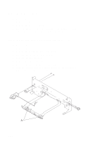
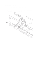
Printhead Carrier Assembly Removal
1. Remove the front cover.
2. Unlock the four printhead cable connectors and disconnect the
printhead cable from the system board.
3. Remove the retainer from the right end of the carrier guide rod.
4. Slide the carrier guide rod to the left, out of the printer.
5. Lift the carrier out of the printer.
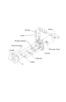
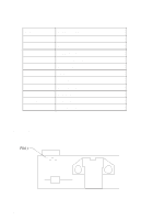
Printhead Rubber Backer Removal
1. Remove the front cover.
2. Remove the printhead carrier assembly.
3. Separate the cradle from the printhead carrier assembly by
pushing out the cradle latches [A].
4. Remove the rubber backer and paper deflector from under the
printhead carrier cable.
Note:
Use the illustration to assemble the carrier parts in the correct
sequence.