Lexmark 7000 Color Jetprinter Service Manual - Page 26
Celsius, or the message Thermal Sensor Not, Thermal Sensor Not Installed message prints
 |
View all Lexmark 7000 Color Jetprinter manuals
Add to My Manuals
Save this manual to your list of manuals |
Page 26 highlights
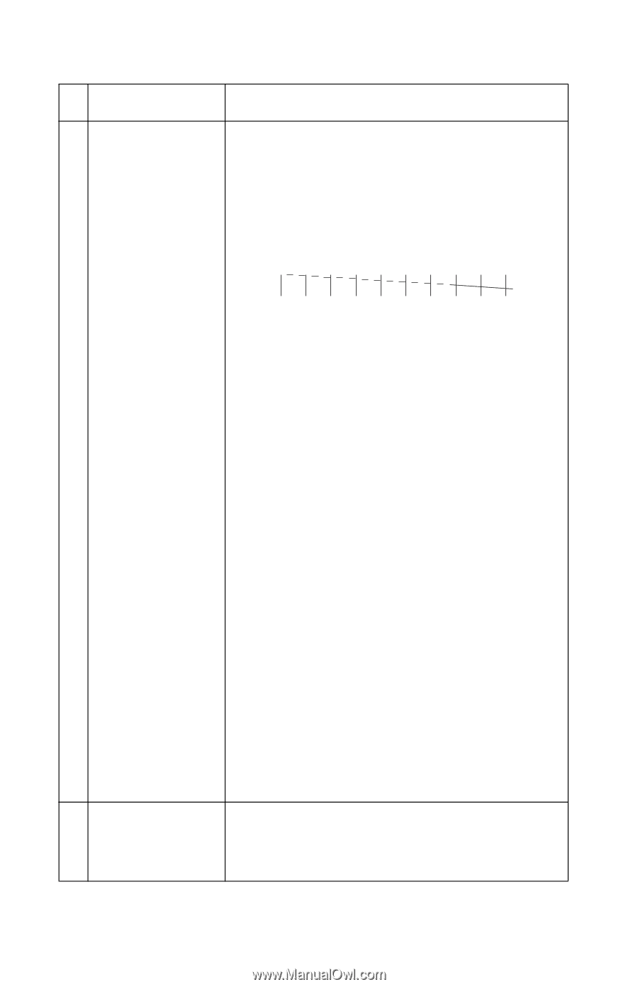
4092-001 FRU 3 System Board Printhead Cable Rubber Backer Thermal Sensor Action • Perform the "Test Page" on page 3-7. Look for a break in the diagonal line of the test pattern. A broken line indicates one or more print nozzles are not working. Run the test again to verify the failure. If there are even breaks in the diagonal line similar to the pattern shown below, replace the system board. 4 Maintenance Station If there is a single break or random breaks in the diagonal line check the following: • Check the gold-plated contacts, on the end of the cable that connect to the carrier, for dirt and wear. Use only a clean dry cloth to clean the contacts. Also check the cable for damage. You may need to remove the cable from the carrier to inspect it. • A worn rubber backer results in poor contact between the printhead cable and the print cartridge. Check the rubber backer for wear. • Refer to the test page. The temperature value in Celsius, or the message "Thermal Sensor Not Installed" is printed. If the thermal sensor is not installed or malfunctioning, and the printer is operating in a warm environment > 104F (40C), excessive ink may flow from the cartridge. Be sure the thermal sensor is connected to J7 on the system board. If the thermal sensor is connected and a "Thermal Sensor Not Installed" message prints, replace the thermal sensor. Note: Printing slows to prevent overheating and excessive ink flow, when the temperature is above the normal operating range, or when printing complex graphics. The normal operating temperature range is 60 F to 90 F (16 C to 32 C). Intermittent nozzle failures can be caused by worn parts in the maintenance station. Perform the "Maintenance Station Service Check" on page 2-7, then return to this check. 2-13
-
 1
1 -
2
-
3
-
4
-
5
-
6
-
7
-
8
-
9
-
10
-
11
-
12
-
13
-
14
-
15
-
16
-
17
-
18
-
19
-
20
-
 21
21 -
 22
22 -
 23
23 -
 24
24 -
 25
25 -
 26
26 -
 27
27 -
 28
28 -
 29
29 -
 30
30 -
 31
31 -
32
-
33
-
34
-
35
-
36
-
37
-
38
-
39
-
40
-
41
-
42
-
43
-
44
-
45
-
46
-
47
-
48
-
49
-
50
-
51
-
52
-
53
-
54
-
55
-
56
-
57
-
58
-
59
-
60
-
61
-
62
-
63
-
64
-
65
-
66
-
67
-
68
-
69
-
70
-
71
-
72
-
73
-
74
-
75
-
76
-
77
-
78
-
79
-
80
-
81
 |
 |