Lexmark 7000 Color Jetprinter Service Manual - Page 54
Printhead Carrier Assembly Removal, Printhead Rubber Backer Removal
 |
View all Lexmark 7000 Color Jetprinter manuals
Add to My Manuals
Save this manual to your list of manuals |
Page 54 highlights
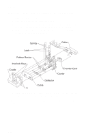
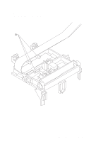
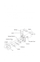
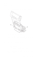
4092-001 Printhead Carrier Assembly Removal 1. Remove the front cover. 2. Unlock the three printhead cable connectors and disconnect the printhead cable from the system board. 3. Remove the screws from the ends of the carrier guide rod and move the carrier to the left. 4. Remove the carrier guide rod by lifting the right end of the rod while spreading the right side of the carrier frame. 5. Remove the carrier assembly by lifting upward, taking care to clear the encoder strip before pulling the carrier assembly out. Printhead Rubber Backer Removal 1. Remove the front cover. 2. Remove the printhead carrier assembly. 3. Separate the cradle from the printhead carrier assembly by pushing out the cradle latches [A]. 4. Remove the rubber backer and paper deflector from under the printhead carrier cable. Note: Use the illustration to assemble the carrier parts in the correct sequence. 4-19
-
 1
1 -
2
-
3
-
4
-
5
-
6
-
7
-
8
-
9
-
10
-
11
-
12
-
13
-
14
-
15
-
16
-
17
-
18
-
19
-
20
-
21
-
22
-
23
-
24
-
25
-
26
-
27
-
28
-
29
-
30
-
31
-
32
-
33
-
34
-
35
-
36
-
37
-
38
-
39
-
40
-
41
-
42
-
43
-
44
-
45
-
46
-
47
-
48
-
 49
49 -
 50
50 -
 51
51 -
 52
52 -
 53
53 -
 54
54 -
 55
55 -
 56
56 -
 57
57 -
 58
58 -
 59
59 -
60
-
61
-
62
-
63
-
64
-
65
-
66
-
67
-
68
-
69
-
70
-
71
-
72
-
73
-
74
-
75
-
76
-
77
-
78
-
79
-
80
-
81
 |
 |
