Lexmark 7000 Color Jetprinter Service Manual - Page 39
Carrier Frame Assembly Removal, Remove the four screws
 |
View all Lexmark 7000 Color Jetprinter manuals
Add to My Manuals
Save this manual to your list of manuals |
Page 39 highlights
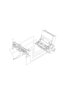
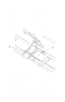
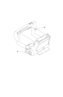
4092-001 Carrier Frame Assembly Removal 1. Remove the front cover. 2. Remove the rear cover. 3. Remove the base assembly. 4. Disconnect the paper feed motor and power supply connectors from the system board. 5. Remove the four screws [A] securing the carrier frame to the left and right side frames and remove the carrier frame assembly. Repair Information 4-4
-
 1
1 -
2
-
3
-
4
-
5
-
6
-
7
-
8
-
9
-
10
-
11
-
12
-
13
-
14
-
15
-
16
-
17
-
18
-
19
-
20
-
21
-
22
-
23
-
24
-
25
-
26
-
27
-
28
-
29
-
30
-
31
-
32
-
33
-
 34
34 -
 35
35 -
 36
36 -
 37
37 -
 38
38 -
 39
39 -
 40
40 -
 41
41 -
 42
42 -
 43
43 -
 44
44 -
45
-
46
-
47
-
48
-
49
-
50
-
51
-
52
-
53
-
54
-
55
-
56
-
57
-
58
-
59
-
60
-
61
-
62
-
63
-
64
-
65
-
66
-
67
-
68
-
69
-
70
-
71
-
72
-
73
-
74
-
75
-
76
-
77
-
78
-
79
-
80
-
81
 |
 |

Repair Information 4-4
4092-001
Carrier Frame Assembly Removal
1.
Remove the front cover.
2.
Remove the rear cover.
3.
Remove the base assembly.
4.
Disconnect the paper feed motor and power supply connectors
from the system board.
5.
Remove the four screws [
A
] securing the carrier frame to the left
and right side frames and remove the carrier frame assembly.