Lexmark X3330 Service Manual - Page 32
CIS module assembly service check, CIS Module
 |
View all Lexmark X3330 manuals
Add to My Manuals
Save this manual to your list of manuals |
Page 32 highlights
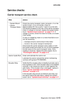
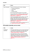
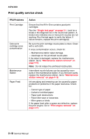
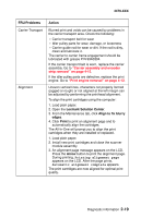
4479-XXX FRU Carrier Assembly Action Check the following parts for wear or damage: • Printhead cartridge latch • Latch spring • Carrier • Printhead cables Ensure that all printhead cables are fully seated. If any of these parts are defective, replace the carrier assembly. Go to "Carrier assembly and encoder strip removal" on page 4-15. Check the gold-plated contacts located on the inside (rear) of the printhead carrier for dirt, wear, and damage. Use a clean, dry cloth to clean the contacts. If the gold contacts are damaged, replace the carrier assembly. Go to "Carrier assembly and encoder strip removal" on page 4-15. If the symptom remains, replace the system board. Go to "System board removal" on page 4-17. CIS module assembly service check FRU CIS Module Assembly Action If the CIS module does not move, ensure that the belt is installed and is not binding. If the CIS module still does not move, replace the system board. Go to "System board removal" on page 4-17. If the lamp does not come on as the CIS module assembly is scanning, check connector J10 on the system board. If connection is okay and the problem remains, replace the scanner module assembly. Go to "Scanner module assembly removal" on page 4-10. 2-14 Service Manual
-
 1
1 -
2
-
3
-
4
-
5
-
6
-
7
-
8
-
9
-
10
-
11
-
12
-
13
-
14
-
15
-
16
-
17
-
18
-
19
-
20
-
21
-
22
-
23
-
24
-
25
-
26
-
 27
27 -
 28
28 -
 29
29 -
 30
30 -
 31
31 -
 32
32 -
 33
33 -
 34
34 -
 35
35 -
 36
36 -
 37
37 -
38
-
39
-
40
-
41
-
42
-
43
-
44
-
45
-
46
-
47
-
48
-
49
-
50
-
51
-
52
-
53
-
54
-
55
-
56
-
57
-
58
-
59
-
60
-
61
-
62
-
63
-
64
-
65
-
66
-
67
-
68
-
69
-
70
-
71
-
72
-
73
-
74
-
75
-
76
 |
 |