Lexmark X342N Service Manual - Page 123
Scanner base assembly removal, Rear cover removal on Modem card removal
 |
UPC - 734646256292
View all Lexmark X342N manuals
Add to My Manuals
Save this manual to your list of manuals |
Page 123 highlights
Scanner base assembly removal 1. Remove rear cover. See"Rear cover removal" on page 4-5. 2. Remove the modem card. See "Modem card removal" on page 4-54. 3. Disconnect the operator panel cable (A) from J5 on the controller card. 7003-XXX 4. Disconnect the 18 and 22 pin ribbon cables (B) from connectors J1 and J4 on the controller card. 5. Disconnect the ADF cable from connector J3 on the controller card. 6. Remove the modem card. See "Modem card removal" on page 4-54. Repair information 4-51
-
 1
1 -
2
-
3
-
4
-
5
-
6
-
7
-
8
-
9
-
10
-
11
-
12
-
13
-
14
-
15
-
16
-
17
-
18
-
19
-
20
-
21
-
22
-
23
-
24
-
25
-
26
-
27
-
28
-
29
-
30
-
31
-
32
-
33
-
34
-
35
-
36
-
37
-
38
-
39
-
40
-
41
-
42
-
43
-
44
-
45
-
46
-
47
-
48
-
49
-
50
-
51
-
52
-
53
-
54
-
55
-
56
-
57
-
58
-
59
-
60
-
61
-
62
-
63
-
64
-
65
-
66
-
67
-
68
-
69
-
70
-
71
-
72
-
73
-
74
-
75
-
76
-
77
-
78
-
79
-
80
-
81
-
82
-
83
-
84
-
85
-
86
-
87
-
88
-
89
-
90
-
91
-
92
-
93
-
94
-
95
-
96
-
97
-
98
-
99
-
100
-
101
-
102
-
103
-
104
-
105
-
106
-
107
-
108
-
109
-
110
-
111
-
112
-
113
-
114
-
115
-
116
-
117
-
 118
118 -
 119
119 -
 120
120 -
 121
121 -
 122
122 -
 123
123 -
 124
124 -
 125
125 -
 126
126 -
 127
127 -
 128
128 -
129
-
130
-
131
-
132
-
133
-
134
-
135
-
136
-
137
-
138
-
139
-
140
-
141
-
142
-
143
-
144
-
145
-
146
-
147
-
148
-
149
-
150
-
151
-
152
-
153
-
154
-
155
-
156
-
157
-
158
-
159
-
160
-
161
-
162
-
163
 |
 |
Repair information
4-51
7003-XXX
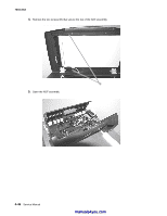
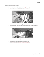
Scanner base assembly removal
1.
Remove rear cover. See
“Rear cover removal” on page 4-5
.
2.
Remove the modem card. See
“Modem card removal” on page 4-54
.
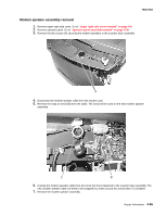
3.
Disconnect the operator panel cable (A) from J5 on the controller card.
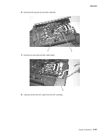
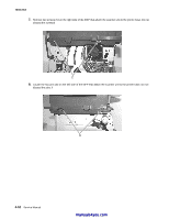
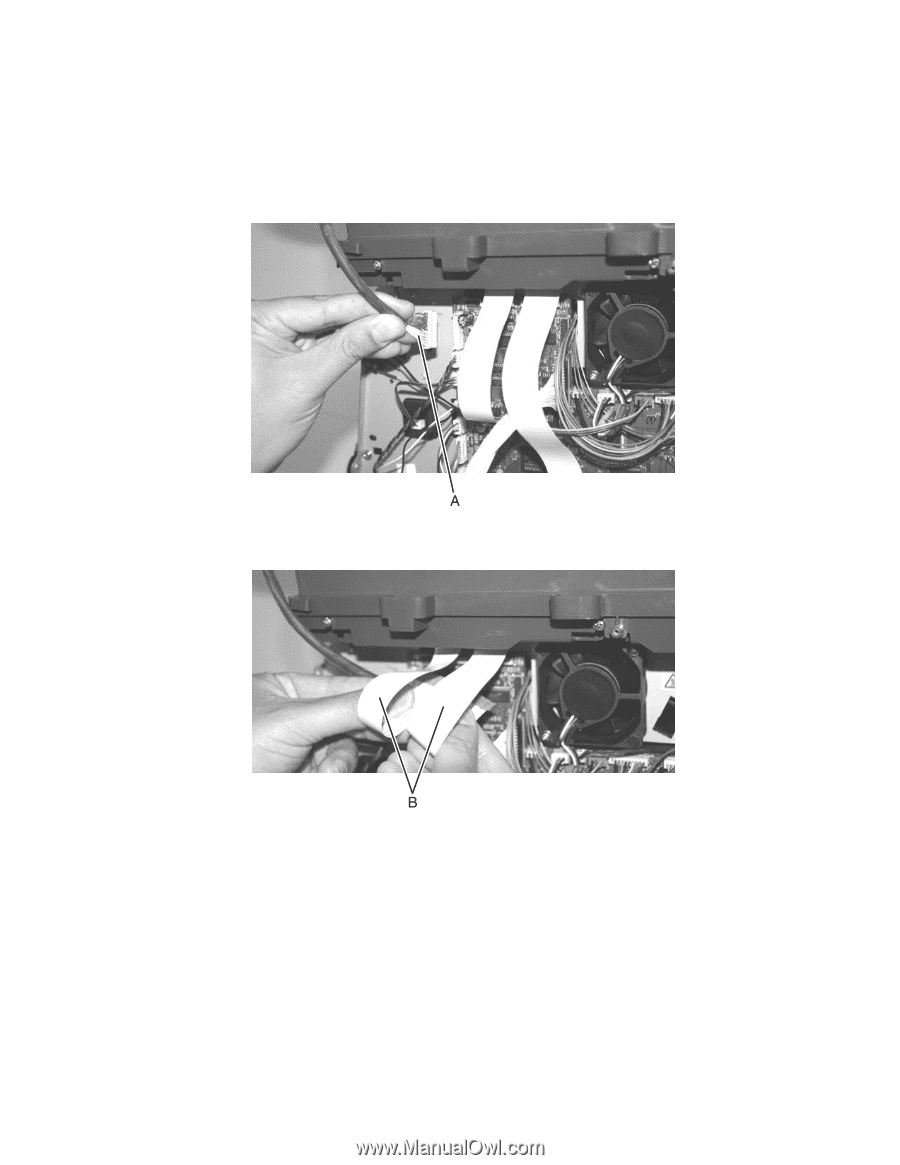
4.
Disconnect the 18 and 22 pin ribbon cables (B) from connectors J1 and J4 on the controller card.
5.
Disconnect the ADF cable from connector J3 on the controller card.
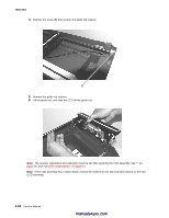
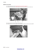
6.
Remove the modem card. See
“Modem card removal” on page 4-54
.