Lexmark X342N Service Manual - Page 133
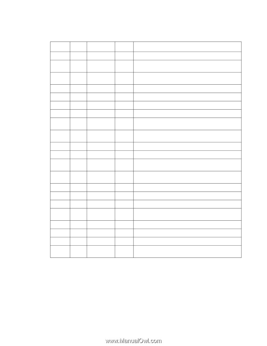
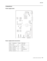
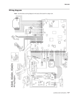
Controller card connections, J69, J5, J1, and J4.
 |
UPC - 734646256292
View all Lexmark X342N manuals
Add to My Manuals
Save this manual to your list of manuals |
Page 133 highlights
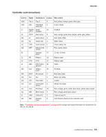
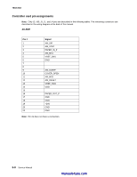
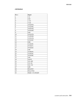
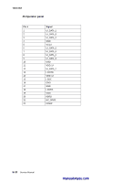
7003-XXX Controller card connections Conn # Name Connects to # wires Wire colors J100 Tray 2 Tray 2 6 Red, yellow, orange, green, blue, grey J101 SOL Paperfeed 4 solenoids 2 red, 2 black J7 HVPS/ Power 10 10 black LVPS Supplies J9 XPRT Main motor 9 Red, orange, green, blue, purple, white, grey, yellow J20 IN Input sensor 3 Red, white, black J14 SC Smart chip 2 White, black J17 TNR Toner sensor 3 Green, black, red J18 MPF Manual feed 3 sensor Red, purple, black J5 Operator 22 12 red, 10 white panel J1 FB Flatbed 18 Ribbon cable J4 CCD CCD 22 Ribbon cable J3 ADF ADF motor/ 21 Cable sensors J69 FAX Modem board 30 30 White J10 EXIT Exit sensor 3 Red, blue, black J19 Fan Fan 3 Black, red, white J15 TH1 Thermistor 2 2 black J13 CO Cover open 3 sensor Yellow, red, black J12 LSU Printhead 10 Red, orange, green, white, blue, black, yellow, grey, purple J11 MM Mirror motor 5 Red, orange, green grey, yellow J2 USB USB to PC 4 Cable to host PC J44 NET Network 0 Card Card mounts directly to the controller card. Note: "Controller card pin assignments" on page 5-8 for voltage and signal information for connections J3, J69, J5, J1, and J4. Locations and connections 5-5
-
 1
1 -
2
-
3
-
4
-
5
-
6
-
7
-
8
-
9
-
10
-
11
-
12
-
13
-
14
-
15
-
16
-
17
-
18
-
19
-
20
-
21
-
22
-
23
-
24
-
25
-
26
-
27
-
28
-
29
-
30
-
31
-
32
-
33
-
34
-
35
-
36
-
37
-
38
-
39
-
40
-
41
-
42
-
43
-
44
-
45
-
46
-
47
-
48
-
49
-
50
-
51
-
52
-
53
-
54
-
55
-
56
-
57
-
58
-
59
-
60
-
61
-
62
-
63
-
64
-
65
-
66
-
67
-
68
-
69
-
70
-
71
-
72
-
73
-
74
-
75
-
76
-
77
-
78
-
79
-
80
-
81
-
82
-
83
-
84
-
85
-
86
-
87
-
88
-
89
-
90
-
91
-
92
-
93
-
94
-
95
-
96
-
97
-
98
-
99
-
100
-
101
-
102
-
103
-
104
-
105
-
106
-
107
-
108
-
109
-
110
-
111
-
112
-
113
-
114
-
115
-
116
-
117
-
118
-
119
-
120
-
121
-
122
-
123
-
124
-
125
-
126
-
127
-
 128
128 -
 129
129 -
 130
130 -
 131
131 -
 132
132 -
 133
133 -
 134
134 -
 135
135 -
 136
136 -
 137
137 -
 138
138 -
139
-
140
-
141
-
142
-
143
-
144
-
145
-
146
-
147
-
148
-
149
-
150
-
151
-
152
-
153
-
154
-
155
-
156
-
157
-
158
-
159
-
160
-
161
-
162
-
163
 |
 |