Lexmark X342N Service Manual - Page 127
Modem speaker assembly removal, Upper right side cover removal
 |
UPC - 734646256292
View all Lexmark X342N manuals
Add to My Manuals
Save this manual to your list of manuals |
Page 127 highlights
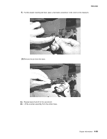
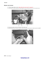
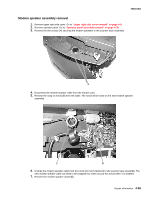
7003-XXX Modem speaker assembly removal 1. Remove upper right side cover. Go to "Upper right side cover removal" on page 4-8. 2. Remove operator panel. Go to "Operator panel assembly removal" on page 4-30. 3. Remove the two screws (A) securing the modem speakers to the scanner base assembly. 4. Disconnect the modem speaker cable from the modem card. 5. Remove the snap on toroid (B) from the cable. The toroid will be used on the new modem speaker assembly. 6. Unwrap the modem speaker cable from the toroid (C) that is fastened to the scanner base assembly. The new modem speaker cable will need to be wrapped four times around this toroid when it is installed. 7. Remove the modem speaker assembly. Repair information 4-55
-
 1
1 -
2
-
3
-
4
-
5
-
6
-
7
-
8
-
9
-
10
-
11
-
12
-
13
-
14
-
15
-
16
-
17
-
18
-
19
-
20
-
21
-
22
-
23
-
24
-
25
-
26
-
27
-
28
-
29
-
30
-
31
-
32
-
33
-
34
-
35
-
36
-
37
-
38
-
39
-
40
-
41
-
42
-
43
-
44
-
45
-
46
-
47
-
48
-
49
-
50
-
51
-
52
-
53
-
54
-
55
-
56
-
57
-
58
-
59
-
60
-
61
-
62
-
63
-
64
-
65
-
66
-
67
-
68
-
69
-
70
-
71
-
72
-
73
-
74
-
75
-
76
-
77
-
78
-
79
-
80
-
81
-
82
-
83
-
84
-
85
-
86
-
87
-
88
-
89
-
90
-
91
-
92
-
93
-
94
-
95
-
96
-
97
-
98
-
99
-
100
-
101
-
102
-
103
-
104
-
105
-
106
-
107
-
108
-
109
-
110
-
111
-
112
-
113
-
114
-
115
-
116
-
117
-
118
-
119
-
120
-
121
-
 122
122 -
 123
123 -
 124
124 -
 125
125 -
 126
126 -
 127
127 -
 128
128 -
 129
129 -
 130
130 -
 131
131 -
 132
132 -
133
-
134
-
135
-
136
-
137
-
138
-
139
-
140
-
141
-
142
-
143
-
144
-
145
-
146
-
147
-
148
-
149
-
150
-
151
-
152
-
153
-
154
-
155
-
156
-
157
-
158
-
159
-
160
-
161
-
162
-
163
 |
 |
Repair information
4-55
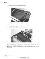
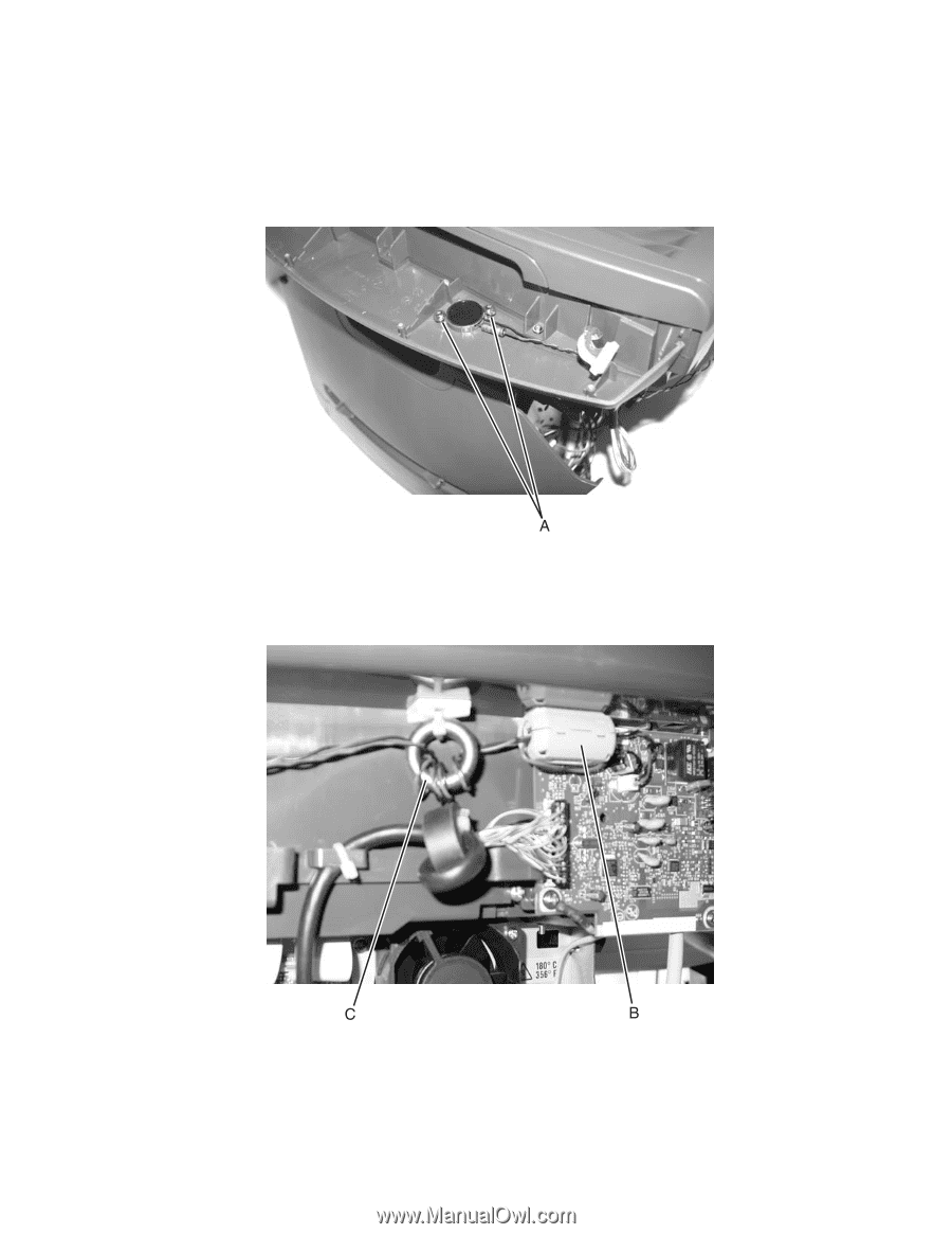
7003-XXX
Modem speaker assembly removal
1.
Remove upper right side cover. Go to
“Upper right side cover removal” on page 4-8
.
2.
Remove operator panel. Go to
“Operator panel assembly removal” on page 4-30
.
3.
Remove the two screws (A) securing the modem speakers to the scanner base assembly.
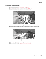
4.
Disconnect the modem speaker cable from the modem card.
5.
Remove the snap on toroid (B) from the cable. The toroid will be used on the new modem speaker
assembly.
6.
Unwrap the modem speaker cable from the toroid (C) that is fastened to the scanner base assembly. The
new modem speaker cable will need to be wrapped four times around this toroid when it is installed.
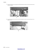
7.
Remove the modem speaker assembly.