Lexmark X342N Service Manual - Page 47
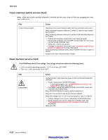
LVPS/HVPS service check, Main motor service check, LVPS portion of board - power cord
 |
UPC - 734646256292
View all Lexmark X342N manuals
Add to My Manuals
Save this manual to your list of manuals |
Page 47 highlights
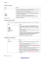
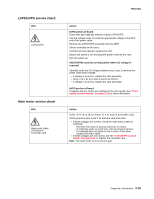
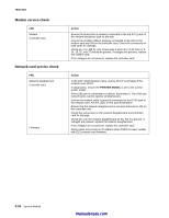
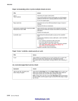
LVPS/HVPS service check FRU LVPS/HVPS Main motor service check FRU Main motor cable LVPS/HVPS Controller card 7003-XXX Action LVPS portion of board Fuses that open typically indicate a faulty LVPS/HVPS. Use the voltage meter to verify the appropriate voltage at the MFP end of the power cable. Remove the LVPS/HVPS assembly from the MFP. Check continuity on the fuses. If either fuse has opened, replace the card. Ensure the switch is off, and plug the power cord into the card. Turn the switch on. CAUTIONThe card has several points where AC voltage is exposed. Carefully verify the AC voltage between pins 1 and 2 matches the power cable (wall) voltage. • If voltage is incorrect, replace the card assembly. • Verify +24 V dc from pins 9 and 10 at CN201. • If voltage is incorrect, replace the card assembly. HVPS portion of board Problems with the HVPS are exhibited in the print quality. See "Print quality service checks" on page 2-31 for more information. Action Verify +24 V dc at J8, pin 8 and +5 V dc at pin 6 (controller card). Verify ground at pins 2 and 7 for both the card and cable. • If these voltages are correct, check the main motor cable for continuity. - Remove rear cover to access connector on motor. - If continuity exists on each wire, call next level of service. - If continuity does not exist on one or more of the wires, replace the motor cable. • If these voltages are not correct, see the "LVPS/HVPS service check" on page 2-25, or replace the controller card. Note: The main motor is not a service part. Diagnostic information 2-25
-
 1
1 -
2
-
3
-
4
-
5
-
6
-
7
-
8
-
9
-
10
-
11
-
12
-
13
-
14
-
15
-
16
-
17
-
18
-
19
-
20
-
21
-
22
-
23
-
24
-
25
-
26
-
27
-
28
-
29
-
30
-
31
-
32
-
33
-
34
-
35
-
36
-
37
-
38
-
39
-
40
-
41
-
 42
42 -
 43
43 -
 44
44 -
 45
45 -
 46
46 -
 47
47 -
 48
48 -
 49
49 -
 50
50 -
 51
51 -
 52
52 -
53
-
54
-
55
-
56
-
57
-
58
-
59
-
60
-
61
-
62
-
63
-
64
-
65
-
66
-
67
-
68
-
69
-
70
-
71
-
72
-
73
-
74
-
75
-
76
-
77
-
78
-
79
-
80
-
81
-
82
-
83
-
84
-
85
-
86
-
87
-
88
-
89
-
90
-
91
-
92
-
93
-
94
-
95
-
96
-
97
-
98
-
99
-
100
-
101
-
102
-
103
-
104
-
105
-
106
-
107
-
108
-
109
-
110
-
111
-
112
-
113
-
114
-
115
-
116
-
117
-
118
-
119
-
120
-
121
-
122
-
123
-
124
-
125
-
126
-
127
-
128
-
129
-
130
-
131
-
132
-
133
-
134
-
135
-
136
-
137
-
138
-
139
-
140
-
141
-
142
-
143
-
144
-
145
-
146
-
147
-
148
-
149
-
150
-
151
-
152
-
153
-
154
-
155
-
156
-
157
-
158
-
159
-
160
-
161
-
162
-
163
 |
 |