Lexmark X342N Service Manual - Page 46
Fuser service check (continued), Hot fuser service check, Action, Step 2: No continuity
 |
UPC - 734646256292
View all Lexmark X342N manuals
Add to My Manuals
Save this manual to your list of manuals |
Page 46 highlights
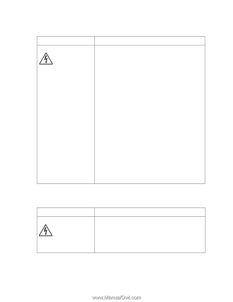
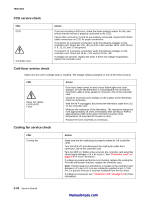
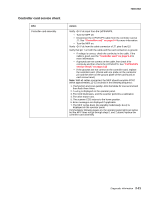
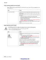
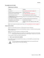
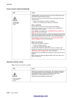
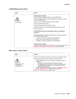
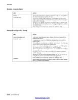
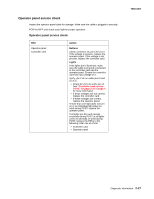
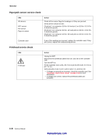
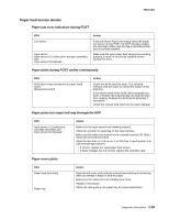
7003-XXX Fuser service check (continued) FRU Lamp cable LVPS/HVPS Fuser Action Unplug the MFP and disconnect the fuser lamp cable plug from the LVPS/HVPS board connector CN102. Check for continuity across the fuser lamp by checking across the connector pins. • If there is continuity, go to Step 1: Continuity. • If there is no continuity, go to Step 2: No continuity. Step 1: Continuity Turn the MFP on with only the fuser power disconnected. Measure the voltage at connector CN102 on the LVPS/HVPS. It should match the line voltage. If line voltage is not present, see "LVPS/HVPS service check" on page 2-25 for more information. Make sure the fuser thermistor is correctly connected to the controller board. If the problem persists, disconnect the thermistor cable at J15 and check for less than +5 V dc on pin 1. Pin 2 should be ground. If line voltage is incorrect on pin 1, see "Controller card service check" on page 2-21 for more information. Step 2: No continuity Check the lamp cable for continuity. • If correct, replace the fuser. • If incorrect, replace the lamp cable. Disconnect the thermistor cable from J15 on the controller card. Measure the resistance across the ends of the thermistor cable. See "Controller card" on page 5-4 for more information. Replace the fuser assembly if the resistance is lower than 1K ohm or shorted. Note: Resistance measures approximately 240K ohms when cool and 1.4K ohms hot. Hot fuser service check Note: Ensure correct fuser is installed. FRU Fuser AC cables LVPS/HVPS Fuser Action Measure the resistance of the thermistor. The resistance measures from approximately 1K ohms immediately after printing or POR to approximately 240K ohms when thermistor reaches room temperature. (It may take 30 minutes to cool.) Replace the fuser assembly as necessary. 2-24 Service Manual manuals4you.com
-
 1
1 -
2
-
3
-
4
-
5
-
6
-
7
-
8
-
9
-
10
-
11
-
12
-
13
-
14
-
15
-
16
-
17
-
18
-
19
-
20
-
21
-
22
-
23
-
24
-
25
-
26
-
27
-
28
-
29
-
30
-
31
-
32
-
33
-
34
-
35
-
36
-
37
-
38
-
39
-
40
-
 41
41 -
 42
42 -
 43
43 -
 44
44 -
 45
45 -
 46
46 -
 47
47 -
 48
48 -
 49
49 -
 50
50 -
 51
51 -
52
-
53
-
54
-
55
-
56
-
57
-
58
-
59
-
60
-
61
-
62
-
63
-
64
-
65
-
66
-
67
-
68
-
69
-
70
-
71
-
72
-
73
-
74
-
75
-
76
-
77
-
78
-
79
-
80
-
81
-
82
-
83
-
84
-
85
-
86
-
87
-
88
-
89
-
90
-
91
-
92
-
93
-
94
-
95
-
96
-
97
-
98
-
99
-
100
-
101
-
102
-
103
-
104
-
105
-
106
-
107
-
108
-
109
-
110
-
111
-
112
-
113
-
114
-
115
-
116
-
117
-
118
-
119
-
120
-
121
-
122
-
123
-
124
-
125
-
126
-
127
-
128
-
129
-
130
-
131
-
132
-
133
-
134
-
135
-
136
-
137
-
138
-
139
-
140
-
141
-
142
-
143
-
144
-
145
-
146
-
147
-
148
-
149
-
150
-
151
-
152
-
153
-
154
-
155
-
156
-
157
-
158
-
159
-
160
-
161
-
162
-
163
 |
 |