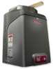
LiftMaster CSW24V CSW24V Manual - Page 11
FEATURES, Plug-in Loop Detector Connectors Model LOOPDETLM Loop Detector - installation manual
 |
View all LiftMaster CSW24V manuals
Add to My Manuals
Save this manual to your list of manuals |
Page 11 highlights
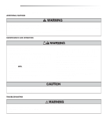
INTRODUCTION FEATURES FEATURES OPERATOR FEATURES • Advanced "Centerpiece" Control Board • EMI AC Power Surge Protection and Filter Board - Main AC voltage input selection: 120 Vac (factory setting) or 240 Vac (field change) • DC motor with extended brush life • AC powered with integrated Evercharge battery backup and management • 24 Vdc accessory power • Programmable with up to 50 remote controls and 2 keyless entries. Compatible with MyQ™ devices and Security✚ 2.0™ codes at either 310, 315, 390 MHz, or 433 MHz • Manual - Secure power failure selection • SAMS compatible • Slow-start and slow-stop gate motion • Reset Switch • Audible Alarm • Internal Heater option (factory installed or field installed) 120 Vac powered ONLY • Integrated internal antenna with external antenna option • Electronic limit adjustment and control from the remote control • Wireless primary/secondary (refer to pages 17-18) CONTROL BOARD FEATURES • Electronic Limit adjustment and control • Adjustable reversal force • Adjustable Timer-to-Close (TTC) • Maximum Run Timer • Bipart Delay switch (dual gate applications) • Feedback and Diagnostic LEDs • Integrated Radio Receiver and 3-Button Station control, six radio frequencies supporting Security✚ 2.0™ EXPANSION BOARD FEATURES • Plug-in Loop Detector Connectors (Model LOOPDETLM Loop Detector) - SHADOW - INTERRUPT - EXIT, with Fail Safe/Fail Secure selection • Quick-Close ON/OFF selection switch • AC Fail Open/Battery selection switch • Low Battery Open/Close selection switch • Anti-Tail ON/OFF selection switch • Single Button Control (SBC) accessory connection • 3-Button station accessory connection • COMMANDS: - OPEN, CLOSE, or STOP: accessory connection and on-board button - FIRE DEPARTMENT OPEN: accessory connection - INTEGRATED RADIO RECEIVER • LOOPS: - EXIT, SHADOW, or INTERRUPT LOOP: accessory connection • AUX Relays (2) each independently selectable operation: - OPEN LIMIT: ON at open limit switch - CLOSE LIMIT: OFF at close limit switch - GATE MOVING: ON with gate moving - PRE-ALERT DELAY: ON 3 seconds before gate motion - TAMPER: ON when gate manually pulled from close limit - POWER: ON with AC or Solar power available - CYCLE QUANTITY: LEDs blink operational cycle count 9
-
 1
1 -
2
-
3
-
4
-
5
-
 6
6 -
 7
7 -
 8
8 -
 9
9 -
 10
10 -
 11
11 -
 12
12 -
 13
13 -
 14
14 -
 15
15 -
 16
16 -
17
-
18
-
19
-
20
-
21
-
22
-
23
-
24
-
25
-
26
-
27
-
28
-
29
-
30
-
31
-
32
-
33
-
34
-
35
-
36
-
37
-
38
-
39
-
40
-
41
-
42
-
43
-
44
-
45
-
46
-
47
-
48
 |
 |
