LiftMaster CSW24V CSW24V Manual - Page 16
Wiring, Wire The Entrapment Protection Devices, Earth Ground Rod - remote
 |
View all LiftMaster CSW24V manuals
Add to My Manuals
Save this manual to your list of manuals |
Page 16 highlights
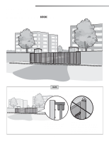
WIRING WIRE THE ENTRAPMENT PROTECTION DEVICES + EARTH GROUND ROD WIRE THE ENTRAPMENT PROTECTION DEVICES Entrapment protection devices are required. Refer to page 5 for more information regarding application. To prevent SERIOUS INJURY or DEATH from a moving gate: • Entrapment protection devices MUST be installed to protect anyone who may come near a moving gate. • Locate entrapment protection devices to protect in BOTH the open and close gate cycles. • Locate entrapment protection devices to protect between moving gate and RIGID objects, such as posts or walls. 1 Connect the entrapment protection device to the EYES EDGE terminal on the control board. These inputs are for pulsed photoelectric sensors and dry contact edges. • Close Photoelectric Sensor Entrapment Protection: Connect wires from the photoelectric sensors to the Inputs on the CLOSE EYES/INTERRUPT terminal. 1 • Close Edge Entrapment Protection: Connect wires from the entrapment protection device to the Inputs on the CLOSE EDGE terminal. • Open Entrapment Protection: Connect wires from the entrapment protection device to the Inputs on the OPEN EYES/EDGE terminal. NOTE: Refer to the "Accessory Features on the Control Board" section on RESET ALARM page 27. TO ERASE LEARNED MONITORED PHOTOELECTRIC SENSORS 1 Remove the photoelectric sensor wires from the terminal block. 2 Press the SET OPEN and SET CLOSE buttons simultaneously until the SET OPEN and SET CLOSE LEDs turn on. 3 Press both SET OPEN and SET CLOSE buttons again to turn off the SET OPEN and SET CLOSE LEDs. NOTE: For dual gate applications repeat the steps above on the other operator. EARTH GROUND ROD Use the proper earth ground rod for your local area. The ground wire must be a single, whole piece of wire. Never splice two wires for the ground wire. If you should cut the ground wire too short, break it, or destroy its integrity, replace it with a single wire length. 1 Install the earth ground rod within 3 feet of the operator. 2 Run wire from the earth ground rod to the operator. To Operator Check national and local codes for proper depth NOTE: If the operator is not grounded properly the range of the remote controls will be reduced. 14
-
 1
1 -
2
-
3
-
4
-
5
-
6
-
7
-
8
-
9
-
10
-
 11
11 -
 12
12 -
 13
13 -
 14
14 -
 15
15 -
 16
16 -
 17
17 -
 18
18 -
 19
19 -
 20
20 -
 21
21 -
22
-
23
-
24
-
25
-
26
-
27
-
28
-
29
-
30
-
31
-
32
-
33
-
34
-
35
-
36
-
37
-
38
-
39
-
40
-
41
-
42
-
43
-
44
-
45
-
46
-
47
-
48
 |
 |
