LiftMaster CSW24V CSW24V Manual - Page 46
Wiring Diagram
 |
View all LiftMaster CSW24V manuals
Add to My Manuals
Save this manual to your list of manuals |
Page 46 highlights
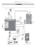
WIRING DIAGRAM To protect against fire and electrocution: • DISCONNECT power and battery BEFORE installing or servicing operator. Field Wiring Edge SLIDE WIRING DIAGRAM 47-36242-10-D ECN: 13199 Reference: 06-36230C 11/17/11 Coaxial Antenna Cable Antenna CONTROL BOARD N.C. Two 12V Solar Panels in Series N.O. COM N.C. LOCK Solenoid Lock (Optional) -+ - + (not provided) LOCK Accessory Power Outlets N.O. COM N.C. Maglock (Optional) (not provided) Butt Splice Switch/5A Breaker L L N Heater GND Red 12V 7AH Battery 12V 7AH Battery Black Red Black Install male insulated faston connectors on solar panel leads. Plug them into the female faston connectors that were connected to the bridge rectifier. Gray Blue Brown Orange - + -- Purple Bridge Rectifier Orange Transformer 375 VA, 24V, 120V N NOTE: The accessory outlet is disabled and GND cannot be used with the 240 Vac option. EMI FILTER/SURGE PROTECTION BOARD Red Black White White Yellow Black Red Black Red Interrrupt Photoelectric Sensors Photoelectric Sensors RESET ALARM Shielded Twisted Pair Cable Primary/Secondary link to other gate operator Ground the shield of the cable to the chassis ground of each operator. Yellow Blue Black Red Identification Resistor Piezo Alarm To Pin 2 To Pin 1 To Pin 6 Run To Pin 5 Stop/Reset Reset Switch 1/2 HP 24 Vdc Motor APS Encoder EXPANSION BOARD 1 N.C. For continued protection against fire: • Replace ONLY with fuse of same type and rating. Field Wiring Black White Black Red 44 Input Power Connection SHADOW INTERRUPT EXIT Wire Loop Wire Loop Wire Loop Field Wiring Field Wiring
-
 1
1 -
2
-
3
-
4
-
5
-
6
-
7
-
8
-
9
-
10
-
11
-
12
-
13
-
14
-
15
-
16
-
17
-
18
-
19
-
20
-
21
-
22
-
23
-
24
-
25
-
26
-
27
-
28
-
29
-
30
-
31
-
32
-
33
-
34
-
35
-
36
-
37
-
38
-
39
-
40
-
 41
41 -
 42
42 -
 43
43 -
 44
44 -
 45
45 -
 46
46 -
 47
47 -
 48
48
 |
 |
