LiftMaster CSW24V CSW24V Manual - Page 17
Power Wiring, 240 Vac Only, American Wire
 |
View all LiftMaster CSW24V manuals
Add to My Manuals
Save this manual to your list of manuals |
Page 17 highlights
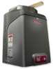
WIRING POWER WIRING This operator can be wired for either 120 Vac or 240 Vac or a solar panel (not provided). Follow the directions according to your application. For dual gate applications, power will have to be connected to each operator. Main power supply and control wiring MUST be run in separate conduits. AMERICAN WIRE GAUGE (AWG) 14 12 10 8 6 4 MAXIMUM WIRE LENGTH (120 VAC) 130 feet 205 feet 325 feet 520 feet 825 feet 1312 feet MAXIMUM WIRE LENGTH (240 VAC) 260 feet 410 feet 650 feet 1040 feet 1650 feet 2624 feet NOTE: Use copper conductors ONLY. POWER WIRING NUMBER OF CYCLES PER DAY Slide Gate Installation (16 ft. 1000 lb. gate) Accessories Single Gate 7AH Batteries 33AH Batteries (standard) (optional) Solenoid Lock 50 mA 100 mA 300 mA TRANSFORMER POWERED BATTERY POWERED Continuous Continuous Continuous Continuous Continuous 100 35 45 45 40 Continuous Continuous Continuous Continuous Continuous 275 230 270 270 260 AC POWER SWITCH The AC Power switch on the operator will turn the incoming 120/240 Vac power ON or OFF. The operator's AC Power switch ONLY turns off AC power to the control board and DOES NOT turn off battery power. AC Power Switch 240 VAC ONLY If using the 240 Vac option a heater cannot be used. The accessory outlet is disabled and cannot be used with the 240 Vac option. 1 Remove the outlet housing from the electrical box by removing the screws (2). 2 Pull the outlet housing out and locate the power wiring connector on the EMI board. 3 Unplug the power wiring connector from the 120 Vac socket (factory default location) and plug it into the 240 Vac socket. 4 Replace the outlet housing by securing with the screws. The operator is now set for 240 Vac operation. Outlet Housing 240 Vac Socket EMI Board Power Wiring Connector (120 Vac Socket, factory default) 15
-
 1
1 -
2
-
3
-
4
-
5
-
6
-
7
-
8
-
9
-
10
-
11
-
 12
12 -
 13
13 -
 14
14 -
 15
15 -
 16
16 -
 17
17 -
 18
18 -
 19
19 -
 20
20 -
 21
21 -
 22
22 -
23
-
24
-
25
-
26
-
27
-
28
-
29
-
30
-
31
-
32
-
33
-
34
-
35
-
36
-
37
-
38
-
39
-
40
-
41
-
42
-
43
-
44
-
45
-
46
-
47
-
48
 |
 |
