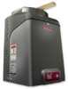
LiftMaster CSW24V CSW24V Manual - Page 15
STANDARD INSTALLATION ONLY, DO NOT run the operator until instructed. - gear box
 |
View all LiftMaster CSW24V manuals
Add to My Manuals
Save this manual to your list of manuals |
Page 15 highlights
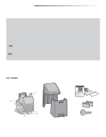
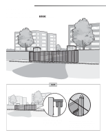
INSTALLATION STANDARD INSTALLATION ONLY + REAR INSTALLATION ONLY STANDARD INSTALLATION ONLY DO NOT run the operator until instructed. 1 Manually open the gate and line up the front bracket so the chain will be level with the idler pulley and parallel to the ground. Weld the front bracket in this position. 1 2 Manually close the gate and line up the rear bracket so the chain will be level with the idler pulley and parallel to the ground. Weld the rear bracket in this position. 3 Route the chain through the operator. 3 4 Connect the chain to the brackets using the eye bolt hardware. Chain should not be too tight or have excessive slack. NOTE: The chain should have no more than 1 inch of sag for every 10 feet of chain length. 2 4 REAR INSTALLATION ONLY DO NOT run the operator until instructed. NOTE: This installation will require two extra idler pulleys. Make sure all exposed pinch points are guarded. Refer to Gate Construction Information on page 4. 1 Move the back pulley to the bottom hole in the operator. 2 Manually close the gate and align the bottom bracket so the chain will be level with the bottom idler pulley and parallel to the ground. Weld the bottom bracket in this position. 3 Align the top bracket so the chain will be level with the top idler pulley 1 4 and parallel to the ground. Weld the upper bracket in this position. 4 Route the chain through the operator. 5 Connect the chain to the brackets using the eye bolt hardware. Chain should not be too tight or have excessive slack. The chain should have no more than 1 inch of sag for every 10 feet of chain length. 5 3 2 Idler Pulley MUST have safety cover. REMOVE THE PIN FROM THE VENT PLUG 1 Remove the pin from the vent plug on the gear box. Vent Plug Pin 13
-
 1
1 -
2
-
3
-
4
-
5
-
6
-
7
-
8
-
9
-
 10
10 -
 11
11 -
 12
12 -
 13
13 -
 14
14 -
 15
15 -
 16
16 -
 17
17 -
 18
18 -
 19
19 -
 20
20 -
21
-
22
-
23
-
24
-
25
-
26
-
27
-
28
-
29
-
30
-
31
-
32
-
33
-
34
-
35
-
36
-
37
-
38
-
39
-
40
-
41
-
42
-
43
-
44
-
45
-
46
-
47
-
48
 |
 |
