LiftMaster SL930 SL930 Manual
LiftMaster SL930 Manual
 |
View all LiftMaster SL930 manuals
Add to My Manuals
Save this manual to your list of manuals |
LiftMaster SL930 manual content summary:
- LiftMaster SL930 | SL930 Manual - Page 1
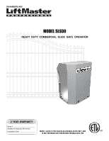
MOMDEOLDSELL9S3L093D0C BB HEAVY DUTY COMMERCIAL SLIDE GATE OPERATOR 2 YEAR WARRANTY Serial located on electrical box cover) Installation Date MODEL SL930 IS FOR VEHICULAR PASSAGE GATES ONLY AND IS NOT INTENDED FOR PEDESTRIAN PASSAGE GATE USE - LiftMaster SL930 | SL930 Manual - Page 2
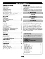
Preparation 9 Mount the Operator 10 CAUTION Install Gate Bracket and Drive Chain 11 Alternate Installation 12 WIRING Power Wiring 13 Battery Backup 14 Control Wiring 15-16 Programming the Radio Receiver 17 Master/Second Wiring 18 Optional Accessory Wiring 19 SL930 Wiring Diagram with Full - LiftMaster SL930 | SL930 Manual - Page 3
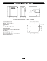
17" 12" The following models are not currently ETL approved: SL930-DC-BB OPERATOR DIMENSIONS Height: 21" Width: 17" Depth: 12" SHIPPING APPLICATIONS • Maximum Gate Weight: 1,500 lbs. • Maximum Gate Length: 40 ft. • Maximum Track Grade: 5 % (1 ft. rise over 20 ft. run) • Maximum Gate Speed: 10"/ - LiftMaster SL930 | SL930 Manual - Page 4
board will deliver can be adjusted for both directions of travel to accommodate the various gate weights that the SL930 operator is recommended for (see page 3). OPERATION The SL930 Full Systems Capability can operate in a AUTO CLOSE TIMER (TIMER ON) or a PUSH-TO-OPEN/PUSH-TO-CLOSE (TIMER OFF - LiftMaster SL930 | SL930 Manual - Page 5
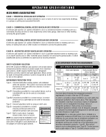
security area or other restricted access locations not servicing the general public, in which unauthorized access is prevented via supervision by security personnel. SAFETY ACCESSORY SELECTION All UL325 compliant LiftMaster gate operators will accept external entrapment protection devices to - LiftMaster SL930 | SL930 Manual - Page 6
part of a gate system. Therefore, safety features must be incorporated into every design. Specific safety features include: • Gate Edges • Screen Mesh • Guards for Exposed Rollers • Vertical Posts • Photoelectric Sensors • Instructional and Precautionary Signage 4. Install the gate operator - LiftMaster SL930 | SL930 Manual - Page 7
OPERATOR WARNINGS SUGGESTED ENTRAPMENT PROTECTION DEVICE LOCATIONS GATE SYSTEM (COMMERCIAL SLIDE GATE) Sentex Telephone Entry System/Access Control Open Edge Close Edge * 1/4" Or As Required For Loop Wire Width *Refer to loop manufacturer's instructions for detailed installation and loop wiring - LiftMaster SL930 | SL930 Manual - Page 8
grill while the gate is operating. They cannot retract their arm and it gets caught between the moving gate grill and the Gate Edge for Open Direction Always Test Gate Edges and Photo Beams Anytime They Are Adjusted or Serviced Gate Edge Pinch-Point Hazard Gate Edge for AVERTISSEMENT Gate - LiftMaster SL930 | SL930 Manual - Page 9
back and forth 2 or 3 times. If the gate operator appears to have any shipping damage, contact a dealer. WARNING To prevent possible SERIOUS INJURY or DEATH: CAUTION • DO NOT connect electric power until instructed to do so. Figure 1 SET REMOTE The operator may be run back and forth by momentarily - LiftMaster SL930 | SL930 Manual - Page 10
" x 10". The cement pad should be at least 6" in depth and extend below frost line. If it is desirable to elevate 1" Cement Pad 16" the gate operator, it may protrude 4" or more above ground (Figure 4). Place the shortest pad edge even with the driveway edge. Place the longer edge of the pad - LiftMaster SL930 | SL930 Manual - Page 11
the switch as this may damage the switches. When finished, make sure the guide plate is properly engaged with the grooves on the limit nuts. Chain Bolt Master Link Self Tapping Screw Figure 10 ADVERTENCIA PRECAUCIÓN Manual Release Circuit Breaker Limit Switch Gate Bracket U-Bolt Limit Nut - LiftMaster SL930 | SL930 Manual - Page 12
The rear mount installation is an excellent way to conceal the chain or operator. The operator is placed in the extreme rear of the gate and the chain never goes across the driveway (Figure 11). The chain only goes from the gate operator to a post or wall beside the driveway. Place shortest edge of - LiftMaster SL930 | SL930 Manual - Page 13
returned to protected. The location of the power disconnect should be service. visible and clearly labeled. • Disconnecting power at the fuse box individual. AVERTISSaEndM/or EdamNagTe to operator. N POWER WIRING CONDUIT ROUTING AVERTISFigSureE1MENT The operator is provided with two knockout - LiftMaster SL930 | SL930 Manual - Page 14
WIRING BATTERY BACKUP If the operator is already factory equipped with a battery backup, only the Right/Left Side switch and Mode 1 are supported (Figure 3). The Right/Left switch simply needs to be set in the same position as the Right/Left switch on the main control board (see page 22). Gate will - LiftMaster SL930 | SL930 Manual - Page 15
device. The device used must provide normally open contacts. These normally open contacts are connected to terminals 5 and 6. These open input terminals will cause the gate operator to open and/or close if the timer switch is in the OFF position. If the timer switch is in the ON position, these open - LiftMaster SL930 | SL930 Manual - Page 16
a common "buss bar" which connects the common terminals of all buttons together so that only one common wire needs to be run back to the gate operator control board. If this is not the case, the common terminals of each button may be connected together with wire. Connect the common terminal or - LiftMaster SL930 | SL930 Manual - Page 17
closed. NEVER permit anyone to cross path of moving gate or door. Security Mode Terminals AVEFRiguTre I1SSEMENT Jumper WARNING Security or replacing the battery. THERE ARE NO OTHER USER SERVICEABLE PARTS. Tested to Comply with FCC Standards FOR HOME OR OFFICE USE. Operation is subject to - LiftMaster SL930 | SL930 Manual - Page 18
WIRING MASTER/SECOND WIRING Connect 115 Volts AC to each SL930 gate operator. Connect the four Master/Second wires from the master circuit board to the second circuit board (Figure 7). Any operator can be used as either a master or a second. Accessories can be connected to the master or second - LiftMaster SL930 | SL930 Manual - Page 19
and make all adjustments with the extended auto close timer knob. Figure 9 WARNING ALARM For added safety, a warning alarm may be installed in the gate operator to give audible warning that the gate is in motion. This will in some cases give extra time to get out of the way of the moving - LiftMaster SL930 | SL930 Manual - Page 20
SL930 WIRING DIAGRAM WITH FULL SYSTEMS CAPABILITY Fail Safe Relay 90 VDC 20 - LiftMaster SL930 | SL930 Manual - Page 21
SL930 WIRING DIAGRAM WITH BATTERY BACKUP 90 VDC 21 - LiftMaster SL930 | SL930 Manual - Page 22
SIDE INSTALLATION ADJUSTMENT Wall Wall Gate Gate RIGHT SIDE INSTALLATION Opener ADJUST TIMER The gate operator is designed to work differently while opening then while closing to optimize safety, so the direction of the operator will need to be set. Setting the operator direction is done by - LiftMaster SL930 | SL930 Manual - Page 23
view of gate operation. All inputs are normally open and momentary, except the stop (N.C.). The following instructions are based upon UL325, and include recommendations for significant increase in safety. *We strongly recommend that you follow the UL guidelines presented throughout the manual. Refer - LiftMaster SL930 | SL930 Manual - Page 24
GATE HARDWARE LOCATOR Guide Roller GR 121 ACCESSORIES Gate End Guide GE 306 Chain Bolt CB 407 V-Track TV 201 Mounting Plate TM 202 V-Wheel VW 201 End Sprocket ES 130 24 - LiftMaster SL930 | SL930 Manual - Page 25
by a LiftMaster operator. Failure to adjust and retest the gate operator professional. properly can increase the risk of INJURY or DEATH. 10. SAVE THESE INSTRUCTIONS. AVERTISSEMENT DESCRIPTION External Entrapment Protection Systems Gate Caution Signs Manual Disconnect Drive Chain Sprockets and - LiftMaster SL930 | SL930 Manual - Page 26
SL930 Full Systems Capability circuit board has been equipped with Visual Feedback LEDs to simplify installation and troubleshooting. These are small lights which are located directly beside the input terminals. These LEDs give visual information to the installer or service normal operating - LiftMaster SL930 | SL930 Manual - Page 27
TROUBLESHOOTING SL930 TROUBLESHOOTING REMOTE CONTROL DOES NOT WORK 1. Check the battery inside of the remote control and/or try another remote control. 2. Check to see which LEDs are illuminated on the circuit board. For normal operating conditions the only LEDs that should be illuminated are the - LiftMaster SL930 | SL930 Manual - Page 28
TROUBLESHOOTING SL930 TROUBLESHOOTING THE GATE WILL NOT STOP OR REVERSE WHEN IT MEETS AN OBSTRUCTION Adjust the gate sensitivity. The operator needs to be adjusted for more sensitivity. This is done by turning the open and close gate sensitivity adjustments clockwise for more sensitivity (see page - LiftMaster SL930 | SL930 Manual - Page 29
OPERATOR NOTES 29 - LiftMaster SL930 | SL930 Manual - Page 30
Battery Charge Breaker, 5 Amp Owner's Manual ITEM PART # A K72-40359 B K74-40084 C K75-30350 D K74-40347 E K74-40065 F K75-40346 G K75-40401 H K75-40403 I K74-40378 SERVICE Sprocket Service Kit Complete with: Sprocket 35B54-1" Bore and Woodruff Key 1/4"x7/8". Operator Cover Service Kit Complete - LiftMaster SL930 | SL930 Manual - Page 31
ILLUSTRATED PARTS - MODEL SL930 I 6 E 7 8 5 D 4 B 10 9 1 C 13 12 A H 2 F G F 11 3 31 - LiftMaster SL930 | SL930 Manual - Page 32
AMERICA FOR INSTALLATION AND SERVICE INFORMATION, CALL OUR TOLL FREE NUMBER 1-800-528-2806 www.liftmaster.com WHEN ORDERING REPAIR PARTS PLEASE SUPPLY THE FOLLOWING INFORMATION: PART NUMBER DESCRIPTION MODEL NUMBER ADDRESS ORDER TO: THE CHAMBERLAIN GROUP, INC. Technical Support Group 6050 Country
-
 1
1 -
 2
2 -
 3
3 -
 4
4 -
 5
5 -
 6
6 -
 7
7 -
8
-
9
-
10
-
11
-
12
-
13
-
14
-
15
-
16
-
17
-
18
-
19
-
20
-
21
-
22
-
23
-
24
-
25
-
26
-
27
-
28
-
29
-
30
-
31
-
32
 |
 |
MODEL SL930 DC BB
HEAVY DUTY COMMERCIAL SLIDE GATE OPERATOR
Serial # ________________________
(located on electrical box cover)
Installation Date__________________
2 YEAR WARRANTY
MODEL SL930 IS FOR VEHICULAR PASSAGE GATES ONLY AND
IS NOT INTENDED FOR PEDESTRIAN PASSAGE GATE USE
MODEL SL930