LiftMaster SL930 SL930 Manual - Page 14
Battery Backup
 |
View all LiftMaster SL930 manuals
Add to My Manuals
Save this manual to your list of manuals |
Page 14 highlights
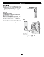
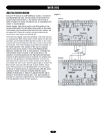
WIRING BATTERY BACKUP If the operator is already factory equipped with a battery backup, only the Right/Left Side switch and Mode 1 are supported (Figure 3). The Right/Left switch simply needs to be set in the same position as the Right/Left switch on the main control board (see page 22). Gate will continue to operate when power is lost. Figure 3 INSTALLATION 1. Disconnect power to operator. 2. Disconnect the brown and red wires from terminals 13 and 14 and insulate the ends of the wires. 3. Attach 14 terminal charger board to terminal screws on the left side of control board and secure using terminal screws. 4. Connect green wire from terminal 2 to terminal 15 of the control board. 5. Connect orange wire from terminal D of the charger board to terminal 18 of the main control board. 6. Connect red wire from terminal A to battery positive (+) and black wire from terminal B to battery negative (-) (Figure 4). Figure 4 (Set same as RIGHT/LEFT switch on control board.) Disconnect these existing wires from 13 and 14. Existing Bridge Rectifier 14
-
 1
1 -
2
-
3
-
4
-
5
-
6
-
7
-
8
-
 9
9 -
 10
10 -
 11
11 -
 12
12 -
 13
13 -
 14
14 -
 15
15 -
 16
16 -
 17
17 -
 18
18 -
 19
19 -
20
-
21
-
22
-
23
-
24
-
25
-
26
-
27
-
28
-
29
-
30
-
31
-
32
 |
 |
