LiftMaster SL930 SL930 Manual - Page 27
Sl930 Troubleshooting
 |
View all LiftMaster SL930 manuals
Add to My Manuals
Save this manual to your list of manuals |
Page 27 highlights
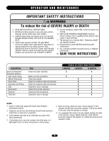
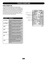
TROUBLESHOOTING SL930 TROUBLESHOOTING REMOTE CONTROL DOES NOT WORK 1. Check the battery inside of the remote control and/or try another remote control. 2. Check to see which LEDs are illuminated on the circuit board. For normal operating conditions the only LEDs that should be illuminated are the stop input at terminal 9 and Limit Switch 1 input if the gate is in the fully open position or Limit Switch 2 input if the gate is in the fully closed position. 3. If any of the input LEDs are illuminated on terminals 4, 5, 7 or 10, disconnect wires from that input terminal that is illuminated until the LED is extinguished to determine which input device may be stuck in an on condition. 4. If it is the radio receiver that appears to be stuck in an on condition, check all remote controls to see if any of them are stuck on. 5. Make sure that there is power (10 to 16 VDC) to the receiver on terminals 8 and 12 and make sure that the circuit breaker button is pressed in. 6. If a click is heard while the remote control is being pressed and there is no response from the operator, check all receiver connections (see page 15). 7. If there is still no response, see GATE WILL NOT OPEN OR CLOSE. GATE TRAVELS TOO FAR OR NOT FAR ENOUGH 1. Adjust the gate sensitivity (see page 22). If the gate sensitivity adjustment is too sensitive, the gate may stop in mid-travel. 2. It may be necessary to lubricate any mechanical parts on the gate including wheels and rollers and clean the track of any debris. 3. Check the limit switch input LEDs on terminals 1 and 3 to see if either one is illuminated. If one of the limit switch input LEDs is illuminated and the gate has traveled too far or not far enough, this indicates that the limits of travel may need adjustment. Adjust the limits of travel (see page 11). This adjustment may change slightly as the chain stretches due to normal wear and it may change dramatically if the chain has been retightened or the limit plate is accidentally left not engaged with the limit nuts. 4. If the limit nut has traveled past a limit switch, check the limit switch and all limit switch connections (see page 20 or 21). 5. Watch the stop input LED on terminal 9 while the gate operator is running and see if the LED flickers or extinguishes. This may indicate a faulty stop input device or a poor connection between the stop input terminal 9 and common. 6. If the stop input LED on terminal 9 flickers or extinguishes check all connections to the stop input device and/or replace faulty device. GATE BEGINS TO OPEN OR CLOSE, THEN STOPS OR REVERSES 1. Adjust the gate sensitivity (see page 22). If the gate sensitivity adjustment is too sensitive, the gate may stop in mid-travel or reverse. 2. It may be necessary to lubricate any mechanical parts on the gate including wheels and rollers and clean the track of any debris. 3. Watch the input LEDs on terminals 4, 5, 7 and 10 while the gate operator is running to see if any of the LEDs flicker or illuminate. 4. If there is an input LED that flickers or illuminates while the gate is running, disconnect the wires one at a time from that input terminal until the LED does not flicker or illuminate to determine which input device may be activating. 5. If it is the radio receiver that appears to be stuck in the on condition, check all remote controls to see if any of them may be stuck on. A stuck transmitter may cause the gate operator to reverse. GATE WILL NOT OPEN OR CLOSE Test the operator to find out whether the open input devices are functioning by following these steps: 1. If a remote control is being used to open the gate, try another remote control or try using a push button if there is one installed. 2. If a push button is being used try using another push button or a remote control. 3. If there is no push button installed the gate may be operated by connecting a jumper wire to terminal 8 and momentarily touching it to terminal 5 or 7. 4. If the remotes are not working, see REMOTE CONTROL DOES NOT WORK. 5. Check the manual release switch to make sure it is in the operate (up) position. 6. Check to see which LEDs are illuminated on the circuit board. For normal operating conditions the only LEDs that should be illuminated are the stop input at terminal 9 and Limit Switch 1 input if the gate is in the fully open position or Limit Switch 2 input if the gate is in the fully closed position. 7. If any of the input LEDs are illuminated on terminals 4, 5, 7 or 10, disconnect wires from that input terminal that is illuminated until the LED is extinguished to determine which input device may be stuck. 8. If the stop input LED on terminal 9 is not illuminated, check the stop input device if any are installed and all connections to the device. If no stop input device is installed make sure that there is a jumper between terminals 8 and 9 and that it is securely fastened. 9. Check the circuit breaker button. If the circuit breaker is tripped, press it back in. 10. Make sure there is power to the circuit board on terminals 13 and 14. 27
-
 1
1 -
2
-
3
-
4
-
5
-
6
-
7
-
8
-
9
-
10
-
11
-
12
-
13
-
14
-
15
-
16
-
17
-
18
-
19
-
20
-
21
-
 22
22 -
 23
23 -
 24
24 -
 25
25 -
 26
26 -
 27
27 -
 28
28 -
 29
29 -
 30
30 -
 31
31 -
 32
32
 |
 |