LiftMaster SL930 SL930 Manual - Page 26
Troubleshoo Ting
 |
View all LiftMaster SL930 manuals
Add to My Manuals
Save this manual to your list of manuals |
Page 26 highlights
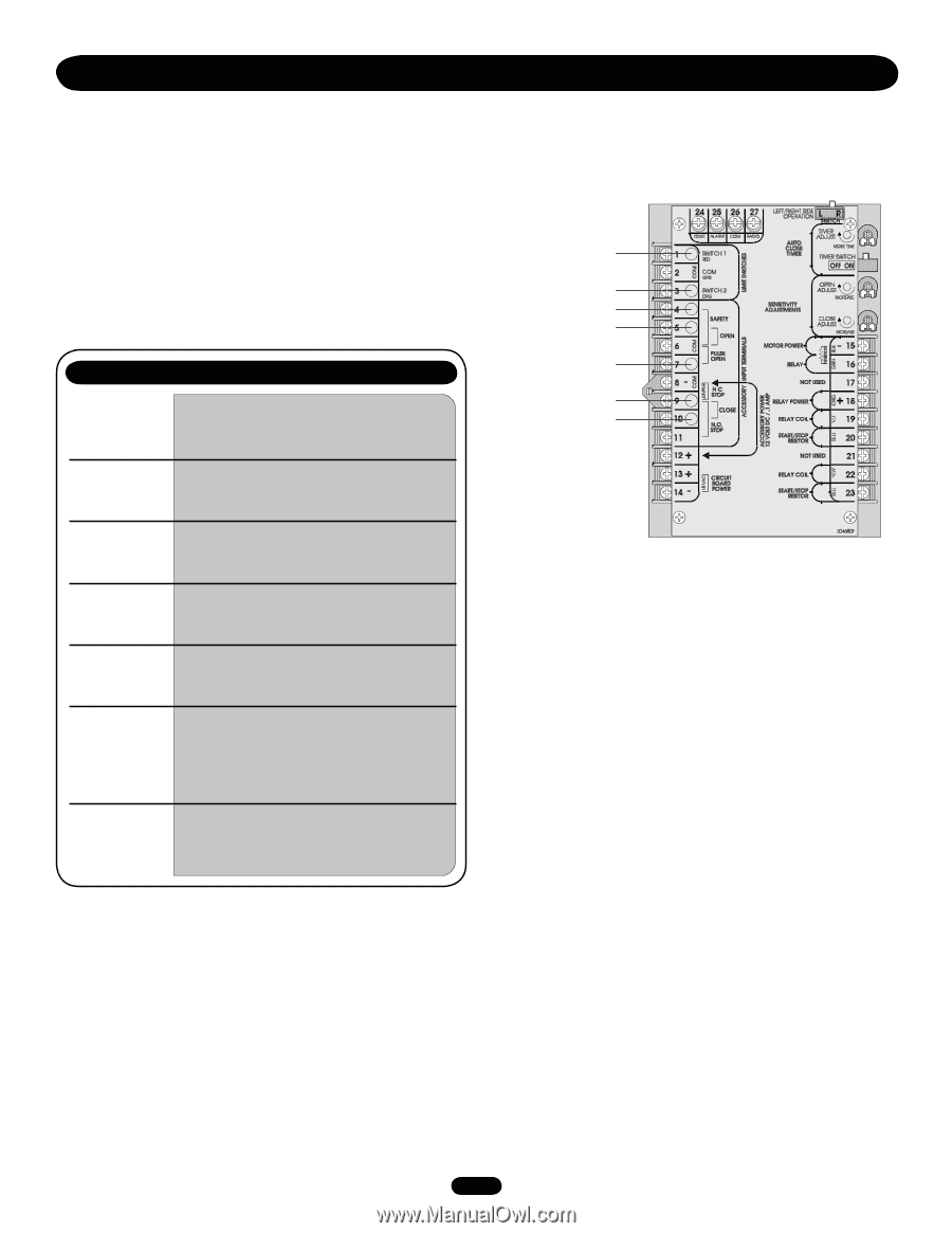
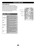
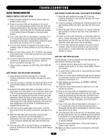
TROUBLESHOOTING VISUAL FEEDBACK LEDS The SL930 Full Systems Capability circuit board has been equipped with Visual Feedback LEDs to simplify installation and troubleshooting. These are small lights which are located directly beside the input terminals. These LEDs give visual information to the installer or service technician indicating what commands are going into the circuit board from devices such as limit switches or from peripheral devices such as radio receivers or safety loops. There are also two LEDs which show output to the motor for both the opening and closing directions. LED INPUT DESCRIPTION Limit Switch 1 Limit Switch 2 Safety Open Pulse Open Stop Close One of the normally open limit switches is pressed in and the gate is in the open position. One of the normally open limit switches is pressed in and the gate is in the closed position. Indicates that there is a closed contact between safety input terminal 4 and common. Indicates that there is a closed contact between open input terminal 5 and common. Indicates that there is a closed contact between Pulse Open input terminal 7 and common. Indicates that there is a closed contact between stop input terminal 9 and common. Under normal operating conditions, this LED must be in the on condition in order for the system to function. Indicates that there is a closed contact between close input terminal 10 and common. Limit Switch 1 LED Limit Switch 2 LED Safety LED Open LED Pulse Open LED Stop LED Close LED 26
-
 1
1 -
2
-
3
-
4
-
5
-
6
-
7
-
8
-
9
-
10
-
11
-
12
-
13
-
14
-
15
-
16
-
17
-
18
-
19
-
20
-
 21
21 -
 22
22 -
 23
23 -
 24
24 -
 25
25 -
 26
26 -
 27
27 -
 28
28 -
 29
29 -
 30
30 -
 31
31 -
32
 |
 |