LiftMaster SL930 SL930 Manual - Page 10
Mount The Operator
 |
View all LiftMaster SL930 manuals
Add to My Manuals
Save this manual to your list of manuals |
Page 10 highlights
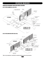
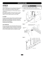
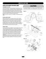
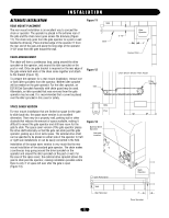
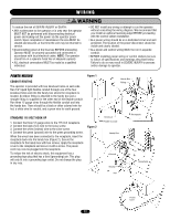
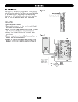
INSTALLATION MOUNT THE OPERATOR Figure 4 Wall CEMENT PAD LOCATION If no concrete surface exists to attach the gate operator to, make a cement pad 16" x 24" x 10". The cement pad should be at least 6" in depth and extend below frost line. If it is desirable to elevate 1" Cement Pad 16" the gate operator, it may protrude 4" or more above ground (Figure 4). Place the shortest pad edge even with the driveway edge. Place the longer edge of the pad 1" away from the gate. 24" OPTIONAL MOUNTING STAND If the steel mounting stand will be used, place the shortest edge of the stand 4" from the driveway edge and place the longest edge of the stand 4-1/2" away from the gate. The top of the steel stand may sit on the ground or the stand may be elevated to keep the operator above snow, flooding etc. Make a post hole and cement the stand in place, making sure the stand is level and square to the gate (Figure 5). Figure 5 10" 16" Wall POSITION GATE OPERATOR If the steel mounting stand was used, simply bolt the gate operator to the stand. If the operator will be mounted to a concrete surface or pad, place the shortest edge of the operator 4" away from the edge of the driveway. Place the longer edge of the gate operator 2-1/2" away from the gate (Figure 6). ANCHOR THE OPERATOR When the gate operator is correctly positioned on the concrete surface or pad, mark the base hole locations onto the cement with a felt tip marker or equivalent. Once marked, move the operator to the side and drill the 4 holes using a 3/8" masonry bit. Place the operator back into position. Insert the four sleeve anchors into the holes and firmly tighten (Figure 7). 4-1/4" 4" Steel Mounting Stand Figure 6 Wall Gate 4" 24" Gate 2-1/2" 4" Figure 7 Gate Gate Operator Sleeve Anchor 10
-
 1
1 -
2
-
3
-
4
-
 5
5 -
 6
6 -
 7
7 -
 8
8 -
 9
9 -
 10
10 -
 11
11 -
 12
12 -
 13
13 -
 14
14 -
 15
15 -
16
-
17
-
18
-
19
-
20
-
21
-
22
-
23
-
24
-
25
-
26
-
27
-
28
-
29
-
30
-
31
-
32
 |
 |
