LiftMaster SL930 SL930 Manual - Page 9
Insta Ll Ation
 |
View all LiftMaster SL930 manuals
Add to My Manuals
Save this manual to your list of manuals |
Page 9 highlights
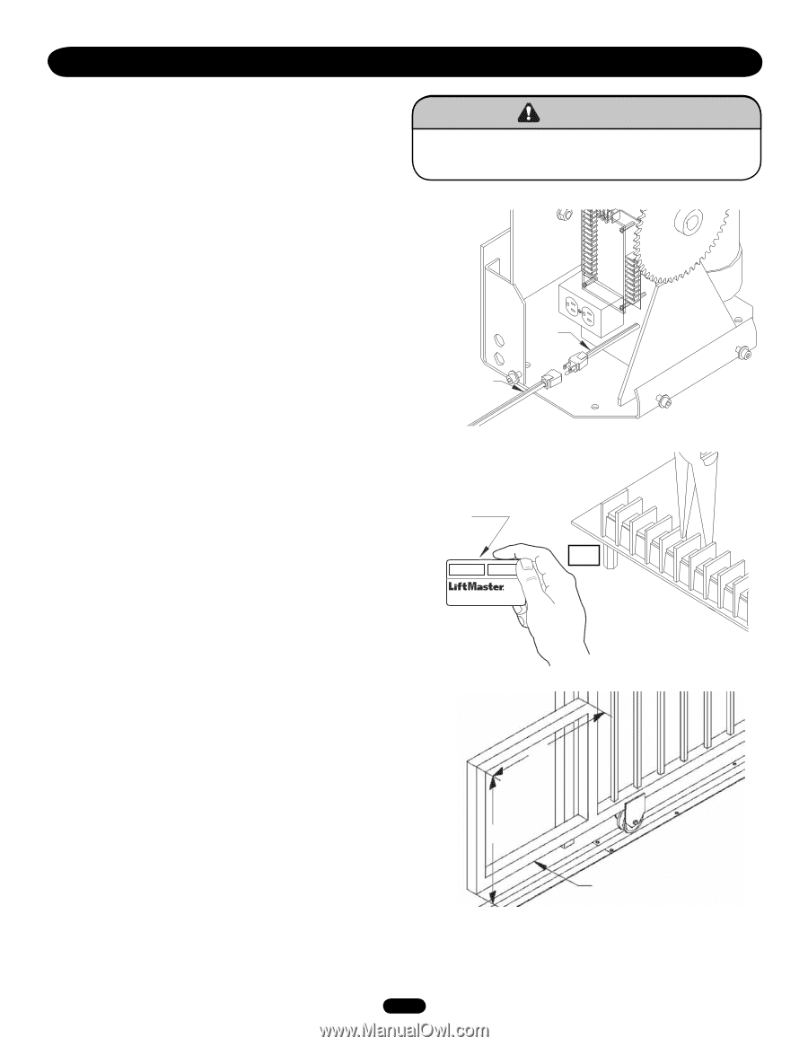
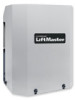
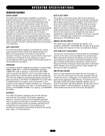
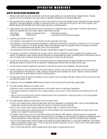
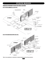
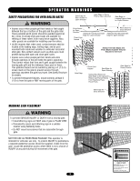
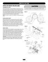
INSTALLATION PREPARATION TEST OPERATOR Remove the gate operator from its package and make sure that all parts are included. Refer to the Carton Inventory and Repair Parts. If any parts appear to be mis.sing, contact dealer Temporarily plug the operator into 115 Volt outlet or extension cord (Figure 1). Before beginning installation, test the gate operator by running the operator back and forth 2 or 3 times. If the gate operator appears to have any shipping damage, contact a dealer. WARNING To prevent possible SERIOUS INJURY or DEATH: CAUTION • DO NOT connect electric power until instructed to do so. Figure 1 SET REMOTE The operator may be run back and forth by momentarily touching the open input terminals together. The terminals can be touched together with a short length of wire, paper clip or needle nose pliers. With full systems capability circuit board, the open input terminals are 5 and 6 (Figure 2). Disconnect power when finished! Extension Cord GATE PREPARATION The tail end of the gate should extend approximately 24" beyond the edge of the driveway. If this is not the case, an extension tail will need to be added to the gate. This will give room for the gate operator. Make the extension tail 24" x 24" (Figure 3). If the gate has not yet been fabricated, add 24" to the length of the gate. Figure 2 Push Remote Control Power Cord AVERTISSEMENT ATTENTION Touch Open Terminals Together Full Systems Board (5 & 6) OR Figure 3 ADVERTENCIA 24" PRECAUCIÓN 24" Extension Tail 9
-
 1
1 -
2
-
3
-
 4
4 -
 5
5 -
 6
6 -
 7
7 -
 8
8 -
 9
9 -
 10
10 -
 11
11 -
 12
12 -
 13
13 -
 14
14 -
15
-
16
-
17
-
18
-
19
-
20
-
21
-
22
-
23
-
24
-
25
-
26
-
27
-
28
-
29
-
30
-
31
-
32
 |
 |