LiftMaster SL930 SL930 Manual - Page 11
Caution - chain
 |
View all LiftMaster SL930 manuals
Add to My Manuals
Save this manual to your list of manuals |
Page 11 highlights
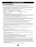
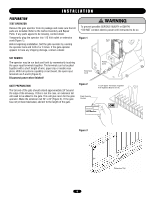
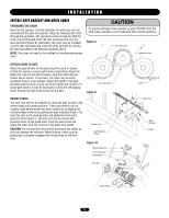
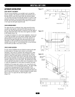
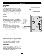
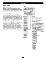
INSTALLATION WARNING INSTALL GATE BRACKET AND DRIVE CHAIN THREADING THE CHAIN Now that the operator is firmly attached, the chain may now be connected to the gate and operator. Begin by threading the chain through the sprockets. The sprockets come arranged so that the chain may be threaded under the idler sprockets and over the drive sprocket (Figure 8). Alternately, the chain may be threaded over the idler sprockets and under the drive sprocket by moving the idler sprockets to the alternate positions above. NOTE: The cover will need to be modified for the alternate arrangement. CAUTION To prevent damage to the operator or gate, DO NOT drive the limit (nuts) actuators on the shaft past their normal positions. Figure 8 Idler Sprocket Alternate Hole ATTACH CHAIN TO GATE Attach the gate bracket to the gate using the round or square U-bolts for round or square gate frames respectively (Figure 9). Attach the chain to the gate brackets using the chain bolt and master link as shown. If necessary, the chain may be easily shortened using a chain breaker. Adjust the height of the gate brackets until the chain is level and firmly tighten the U-bolts. For round gate frames, it may be necessary to drive the self tapping screw through the gate bracket and into the gate. AVERTISSEMENT ATTENTION Drive Sprocket Chain Figure 9 ADJUST LIMITS The limit nuts need to be adjusted to cause the gate to stop in the desired open and closed positions. These adjustments can be roughly made before power has been hooked up by flipping the manual release switch and pushing the gate manually (Figure 10). Push the gate to the open position and adjust the limit nut to press the limit switch in. The limit nuts can be turned after pressing down on the guide plate. Push the gate closed and adjust the other limit nut to press in the other limit switch. CAUTION: Do not allow the limit nuts to travel past the switch as this may damage the switches. When finished, make sure the guide plate is properly engaged with the grooves on the limit nuts. Chain Bolt Master Link Self Tapping Screw Figure 10 ADVERTENCIA PRECAUCIÓN Manual Release Circuit Breaker Limit Switch Gate Bracket U-Bolt Limit Nut Guide Plate 11
-
 1
1 -
2
-
3
-
4
-
5
-
 6
6 -
 7
7 -
 8
8 -
 9
9 -
 10
10 -
 11
11 -
 12
12 -
 13
13 -
 14
14 -
 15
15 -
 16
16 -
17
-
18
-
19
-
20
-
21
-
22
-
23
-
24
-
25
-
26
-
27
-
28
-
29
-
30
-
31
-
32
 |
 |
