Lowrance LMF-400 Installation and Operation Manual - Page 9
Installation - nmea 2000
 |
View all Lowrance LMF-400 manuals
Add to My Manuals
Save this manual to your list of manuals |
Page 9 highlights
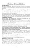
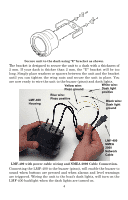
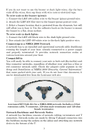
Section 2: Installation Preparation The design of the LMF-400 allows convenient mounting in the dash of your boat, or it can be mounted on any flat panel at least four inches in diameter. To mount the LMF-400 in the dash, first make sure there is sufficient clearance behind the panel in the desired location. At least 3-1/2 inches are needed behind the surface of the dash to clear all connectors and wiring. Recommended Tools and supplies Recommended tools for this job include: hole saw, 3/38" (86 mm) hole saw bit, drill, 1/8" (3 mm) drill bit (for starter hole). Required supplies for this job include: "U" bracket, lock washers and wing nuts (included). Installation Sequence You can install this gauge in some other order if you prefer, but we recommend the installation sequence listed below. 1. Determine the location for the gauge so you can plan how and where to route the cables. This will help you make sure you have enough cable length for the desired configuration. 2. Determine the location of the nearest device on the boat's NMEA 2000 network, along with the route of the gauge's network cable. 3. Determine the location for the alarm buzzer and its wire route. 4. If you want the gauge's backlight to turn on when the dashboard lights are turned on, locate your boat's dash light switch and determine how to route the gauge's dash light wires to it. 5. Install the gauge in a standard 3-3/8 inch (86 mm) hole in the dash. If no 3-3/8 hole available in the dash, you will have to drill a 1/8" pilot hole, then use a hole saw to cut a mounting hole. See instructions for Mounting the Unit below. 6. Connect the buzzer wires and install the buzzer. If desired, connect the dash light wires to the boat's dash light switch. 7. Connect the network cable to the NMEA 2000 network. Mounting the Gauge If no standard mounting hole is available in the dash, drill a 1/8" pilot hole, then cut a 3-3/8 inch (86 mm) diameter mounting hole with a hole saw. A "U" bracket is supplied to hold the unit to the dash. Place it over the threaded studs on the back of the unit and secure it with the lock washers and nylon wing nuts provided with the unit. 3
-
 1
1 -
2
-
3
-
 4
4 -
 5
5 -
 6
6 -
 7
7 -
 8
8 -
 9
9 -
 10
10 -
 11
11 -
 12
12 -
 13
13 -
 14
14 -
15
-
16
-
17
-
18
-
19
-
20
-
21
-
22
-
23
-
24
-
25
-
26
-
27
-
28
-
29
-
30
-
31
-
32
-
33
-
34
-
35
-
36
-
37
-
38
-
39
-
40
-
41
-
42
-
43
-
44
-
45
-
46
-
47
-
48
-
49
-
50
-
51
-
52
-
53
-
54
-
55
-
56
-
57
-
58
-
59
-
60
-
61
-
62
-
63
-
64
-
65
-
66
-
67
-
68
-
69
-
70
-
71
-
72
 |
 |
