MSI 915P COMBO-FR User Guide - Page 18
Hardware Setup - cpu
 |
UPC - 816909005899
View all MSI 915P COMBO-FR manuals
Add to My Manuals
Save this manual to your list of manuals |
Page 18 highlights
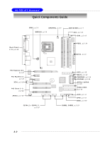
Hardware Setup 5. The CPU has a plastic cap on it to protect the contact from damage. Before you have installed the CPU, always cover it to protect the socket pin. 6. Remove the cap from lever hinge side (as the arrow shows). 7. The pins of socket reveal. Then lift up the load lever. 8. Lift the load lever up and open the load plate. 9. Correctly align the red triangle of CPU clip with the CPU chamfer, the red arrow with the left-side socket edge, and the red spot to the hook of the socket. 10. Put the whole module onto the CPU socket. 2-5
-
 1
1 -
2
-
3
-
4
-
5
-
6
-
7
-
8
-
9
-
10
-
11
-
12
-
 13
13 -
 14
14 -
 15
15 -
 16
16 -
 17
17 -
 18
18 -
 19
19 -
 20
20 -
 21
21 -
 22
22 -
 23
23 -
24
-
25
-
26
-
27
-
28
-
29
-
30
-
31
-
32
-
33
-
34
-
35
-
36
-
37
-
38
-
39
-
40
-
41
-
42
-
43
-
44
-
45
-
46
-
47
-
48
-
49
-
50
-
51
-
52
-
53
-
54
-
55
-
56
-
57
-
58
-
59
-
60
-
61
-
62
-
63
-
64
-
65
-
66
-
67
-
68
-
69
-
70
-
71
-
72
-
73
-
74
-
75
-
76
-
77
-
78
-
79
-
80
-
81
-
82
-
83
-
84
-
85
-
86
-
87
-
88
-
89
-
90
-
91
-
92
-
93
-
94
-
95
-
96
-
97
-
98
-
99
-
100
-
101
-
102
-
103
-
104
-
105
-
106
-
107
-
108
-
109
-
110
-
111
-
112
-
113
-
114
-
115
-
116
-
117
-
118
-
119
-
120
-
121
-
122
-
123
-
124
-
125
-
126
-
127
-
128
-
129
-
130
-
131
-
132
-
133
 |
 |

2-5
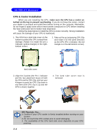
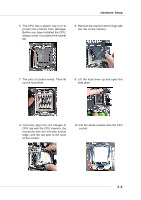
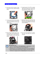
Hardware Setup
5. The CPU has a plastic cap on it to
protect the contact from damage.
Before you have installed the CPU,
always cover it to protect the socket
pin.
6.
Remove the cap from lever hinge side
(as the arrow shows).
7. The pins of socket reveal. Then lift
up the load lever.
8. Lift the load lever up and open the
load plate.
9. Correctly align the red triangle of
CPU clip with the CPU chamfer, the
red arrow with the left-side socket
edge, and the red spot to the hook
of the socket.
10. Put the whole module onto the CPU
socket.