MSI 915P COMBO-FR User Guide - Page 6

BIOS Setup, Introduction to DigiCell

Page 6 highlights

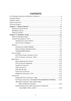
CD-In Connector: JCD1 2-17 Front Panel Connectors: JFP1, JFP2 2-17 IEEE 1394 Connectors: J1394_1, J1394_2, J1394_3 (Optional 2-18 Front Panel Audio Connector: JAUD2 2-18 IrDA Infrared Module Header: JIR1 2-19 Front USB Connectors: JUSB1 & JUSB2 2-19 Chassis Intrusion Switch Connector: JCI1 2-20 D-Bracket™ 2 Connector: JDB1 2-20 Jumpers ...2-21 Clear CMOS Jumper: JBAT1 2-21 Slots ...2-22 PCI Express Slots 2-22 PCI (Peripheral Component Interconnect) Slots 2-22 PCI Interrupt Request Routing 2-23 Chapter 3. BIOS Setup 3-1 Entering Setup ...3-3 Selecting the First Boot Device 3-2 Control Keys 3-3 Getting Help 3-3 Main Menu 3-3 Default Settings 3-3 The Main Menu ...3-4 Standard CMOS Features 3-6 Advanced BIOS Features 3-8 Advanced Chipset Features 3-10 Integrated Peripherals 3-11 Power Management Features 3-14 PNP/PCI Configurations 3-17 H/W Monitor ...3-19 Cell Menu ...3-21 BIOS Setting Password 3-25 Load Fail-Safe/Optimized Defaults 3-26 Chapter 4. Introduction to DigiCell 4-1 Main ...4-2 Introduction 4-2 H/W Diagnostic ...4-4 Communication ...4-5 Software Access Point 4-6 vi

  • 1
  • 2
  • 3
  • 4
  • 5
  • 6
  • 7
  • 8
  • 9
  • 10
  • 11
  • 12
  • 13
  • 14
  • 15
  • 16
  • 17
  • 18
  • 19
  • 20
  • 21
  • 22
  • 23
  • 24
  • 25
  • 26
  • 27
  • 28
  • 29
  • 30
  • 31
  • 32
  • 33
  • 34
  • 35
  • 36
  • 37
  • 38
  • 39
  • 40
  • 41
  • 42
  • 43
  • 44
  • 45
  • 46
  • 47
  • 48
  • 49
  • 50
  • 51
  • 52
  • 53
  • 54
  • 55
  • 56
  • 57
  • 58
  • 59
  • 60
  • 61
  • 62
  • 63
  • 64
  • 65
  • 66
  • 67
  • 68
  • 69
  • 70
  • 71
  • 72
  • 73
  • 74
  • 75
  • 76
  • 77
  • 78
  • 79
  • 80
  • 81
  • 82
  • 83
  • 84
  • 85
  • 86
  • 87
  • 88
  • 89
  • 90
  • 91
  • 92
  • 93
  • 94
  • 95
  • 96
  • 97
  • 98
  • 99
  • 100
  • 101
  • 102
  • 103
  • 104
  • 105
  • 106
  • 107
  • 108
  • 109
  • 110
  • 111
  • 112
  • 113
  • 114
  • 115
  • 116
  • 117
  • 118
  • 119
  • 120
  • 121
  • 122
  • 123
  • 124
  • 125
  • 126
  • 127
  • 128
  • 129
  • 130
  • 131
  • 132
  • 133

vi
CD-In Connector: JCD1
............................................................................
2-17
Front Panel Connectors: JFP1, JFP2
.......................................................
2-17
IEEE 1394 Connectors: J1394_1, J1394_2, J1394_3 (Optional)
...........
2-18
Front Panel Audio Connector: JAUD2
.....................................................
2-18
IrDA Infrared Module Header: JIR1
..........................................................
2-19
Front USB Connectors: JUSB1 & JUSB2
................................................
2-19
Chassis Intrusion Switch Connector: JCI1
.............................................
2-20
D-Bracketâ„¢ 2 Connector: JDB1
..............................................................
2-20
Jumpers
.............................................................................................................
2-21
Clear CMOS Jumper: JBAT1
....................................................................
2-21
Slots
...................................................................................................................
2-22
PCI Express Slots
.....................................................................................
2-22
PCI (Peripheral Component Interconnect) Slots
......................................
2-22
PCI Interrupt Request Routing
..................................................................
2-23
Chapter 3. BIOS Setup
...........................................................................................
3-1
Entering Setup
.....................................................................................................
3-3
Selecting the First Boot Device
.................................................................
3-2
Control Keys
...............................................................................................
3-3
Getting Help
................................................................................................
3-3
Main Menu
...................................................................................................
3-3
Default Settings
..........................................................................................
3-3
The Main Menu
.....................................................................................................
3-4
Standard CMOS Features
...................................................................................
3-6
Advanced BIOS Features
...................................................................................
3-8
Advanced Chipset Features
.............................................................................
3-10
Integrated Peripherals
.......................................................................................
3-11
Power Management Features
..........................................................................
3-14
PNP/PCI Configurations
.....................................................................................
3-17
H/W Monitor
.......................................................................................................
3-19
Cell Menu
............................................................................................................
3-21
BIOS Setting Password
....................................................................................
3-25
Load Fail-Safe/Optimized Defaults
...................................................................
3-26
Chapter 4. Introduction to DigiCell
....................................................................
4-1
Main
.....................................................................................................................
4-2
Introduction
.................................................................................................
4-2
H/W Diagnostic
....................................................................................................
4-4
Communication
.....................................................................................................
4-5
Software Access Point
.......................................................................................
4-6