MSI 970A User Guide - Page 36
CINTRU, Ground
 |
View all MSI 970A manuals
Add to My Manuals
Save this manual to your list of manuals |
Page 36 highlights
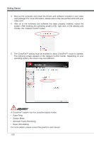
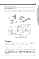
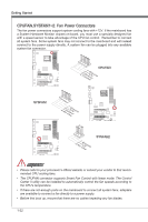
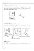
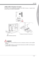
Getting Started JCI1: Chassis Intrusion Connector This connector connects to the chassis intrusion switch cable. If the computer case is opened, the chassis intrusion mechanism will be activated. The system will record this intrusion and a warning message will flash on screen. To clear the warning, you must enter the BIOS utility and clear the record. 1.C2.IGNTroRuUnd JUSB1~3: USB 2.0 Expansion Connector This connector is designed for connecting high-speed USB peripherals such as USB HDDs, digital cameras, MP3 players, printers, modems, and many others. 115V 2.V4C.U6CS.U8BS1.1G0B-r.1No+uCnd 1.V3C.U5CS.U7BS.0G9B-.rN0o+ounPdin * The MB layout in this figure is for reference only. USB 2.0 Bracket (optional) Important Note that the VCC and GND pins must be connected correctly to avoid possible damage. 1-24
-
 1
1 -
2
-
3
-
4
-
5
-
6
-
7
-
8
-
9
-
10
-
11
-
12
-
13
-
14
-
15
-
16
-
17
-
18
-
19
-
20
-
21
-
22
-
23
-
24
-
25
-
26
-
27
-
28
-
29
-
30
-
 31
31 -
 32
32 -
 33
33 -
 34
34 -
 35
35 -
 36
36 -
 37
37 -
 38
38 -
 39
39 -
 40
40 -
 41
41 -
42
-
43
-
44
-
45
-
46
-
47
-
48
-
49
-
50
-
51
-
52
-
53
-
54
-
55
-
56
-
57
-
58
-
59
-
60
-
61
-
62
-
63
-
64
-
65
-
66
-
67
-
68
-
69
-
70
-
71
-
72
-
73
-
74
-
75
-
76
-
77
-
78
-
79
-
80
 |
 |
