MSI E7320 User Manual - Page 24
Connectors - chipset
 |
View all MSI E7320 manuals
Add to My Manuals
Save this manual to your list of manuals |
Page 24 highlights
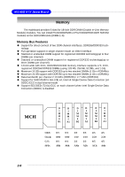
Hardware Setup Connectors The mainboard provides connectors to connect to FDD, IDE HDD, case, LAN, USB Ports, CPU/system power supply fans, ... and etc. Floppy Disk Drive Connector: JFDD The mainboard provides a standard floppy disk drive connector that supports 360K, 720K, 1.2M, 1.44M and 2.88M floppy disk types. JFDD Chassis Intrusion Switch Connector: JCI1 This connector is connected to a 2-pin chassis switch. If the chassis is open, the switch will be short. The system will record this status and show a warning message on the screen. To clear the warning, you must enter the BIOS utility and clear the record. GND CINTRU 1 2 JCI1 Fan Power Connectors: CPUFAN1/2/3, POWERFAN1/2/3/4 The fan power connectors support system cooling fans with +12V. When connecting the wire to the connectors, always note that the red wire is the positive and should be connected to the +12V; the black wire is Ground and should be connected to GND. If the mainboard has a System Hardware Monitor chipset onboard, you must use a specially designed fan with speed sensor to take advantage of the CPU fan control. GND +12V Sensor Sensor +12V GND POWERFAN2/3/4 Sensor +12V GND CPUFAN2/3 CPUFAN1/ POWERFAN1 MSI Reminds You... Always consult the vendors for proper CPU cooling fans. 2-11
-
 1
1 -
2
-
3
-
4
-
5
-
6
-
7
-
8
-
9
-
10
-
11
-
12
-
13
-
14
-
15
-
16
-
17
-
18
-
 19
19 -
 20
20 -
 21
21 -
 22
22 -
 23
23 -
 24
24 -
 25
25 -
 26
26 -
 27
27 -
 28
28 -
 29
29 -
30
-
31
-
32
-
33
-
34
-
35
-
36
-
37
-
38
-
39
-
40
-
41
-
42
-
43
-
44
-
45
-
46
-
47
-
48
-
49
-
50
-
51
-
52
-
53
-
54
-
55
-
56
-
57
-
58
-
59
-
60
-
61
-
62
-
63
-
64
-
65
-
66
-
67
-
68
-
69
-
70
-
71
-
72
-
73
-
74
-
75
-
76
-
77
-
78
-
79
-
80
-
81
-
82
-
83
-
84
-
85
-
86
-
87
-
88
-
89
-
90
-
91
-
92
 |
 |
