Magnavox MRD210 User Manual - Page 1
Magnavox MRD210 Manual
 |
UPC - 037849935385
View all Magnavox MRD210 manuals
Add to My Manuals
Save this manual to your list of manuals |
Page 1 highlights
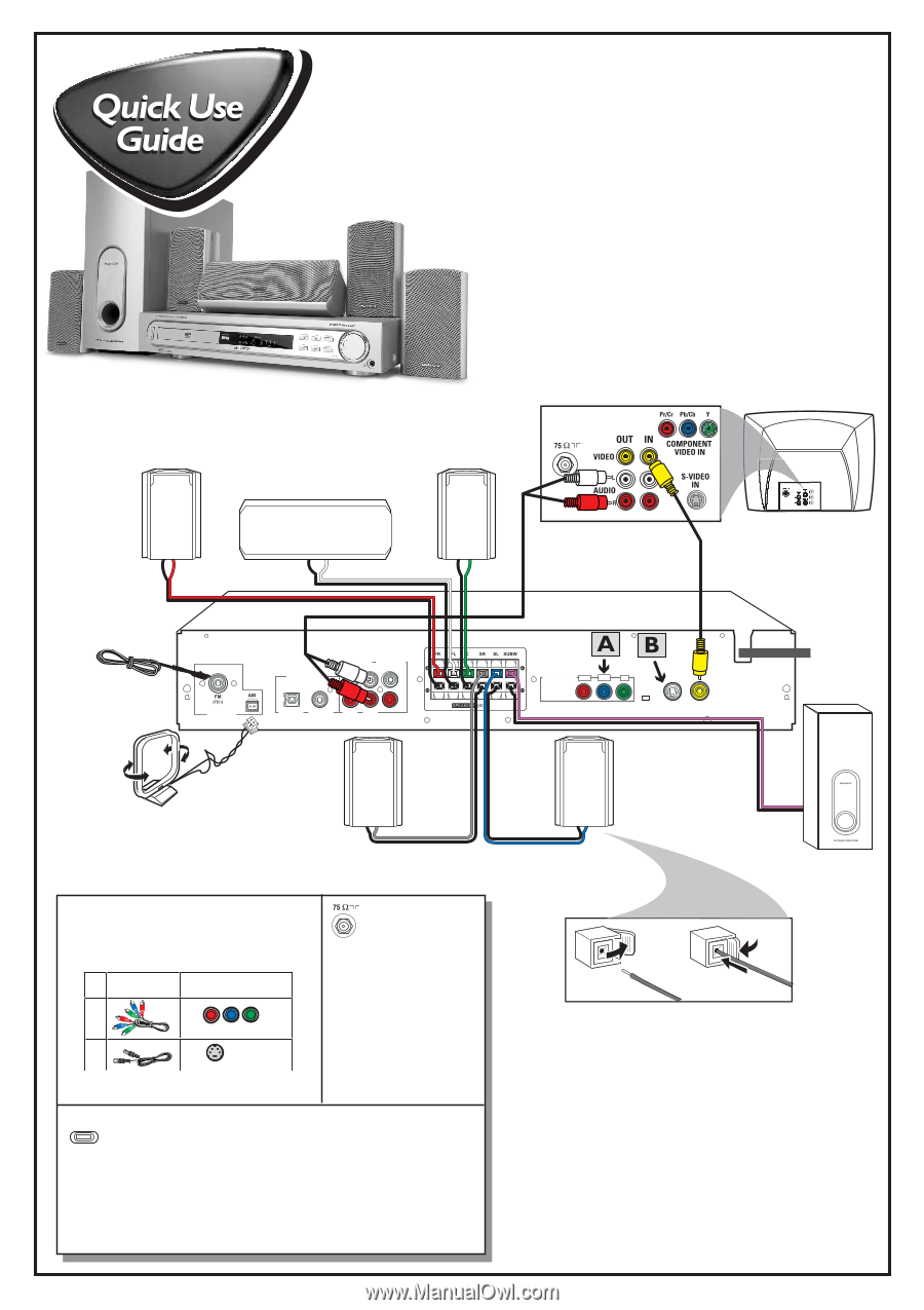
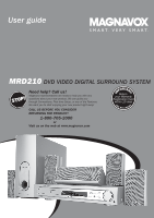
MRD210 MAGNAVOX Printed in China First connect ... Front Speaker (Right) Front Speaker (Left) Center Speaker Pr/Cr Pb/Cb Y FM Antenna AM Loop Antenna AM/FM ANTENNA DIGITAL OUT AUDIO IN AUDIO OUT L R OPTICAL COAXIAL AUX TV COMPONENT VIDEO OUT Pr/Cr Pb/Cb Y P-SCAN OFF ON S-VIDEO VIDEO OUT OUT Rear Speaker (Surround Right) Helpful Hints To obtain a better picture quality effect, you can choose to connect an extra video connection if your TV has the same input connector: A or B. Use this If your TV has video cable(s) this video input jack(s) A Component Video not supplied B S-VIDEO IN If your TV has only a single Antenna In jack, you will need an ANTENNA IN accessory RF modulator. The RF modulator converts the video from the DVD system so it can play through the TV's Antenna connector. Refer to your owner's manual for proper connection (refer to page 9 in the owner's manual.) P-SCAN Do not switch the P-SCAN to 'ON' position, unless you have connected the DVD system to a Progressive Scan TV using the ON OFF Component (Pr Pb Y) video jacks. When listening to TV programs, press TV/AV button on the remote to set the DVD system to TV/AV mode in order for the sound to be heard. For connecting to a VCR, see page 9 in the owner's manual for more details. Rear Speaker (Surround Left) Passive Subwoofer PUSH 1 OUT 2 PUSH IN Connecting Speaker Cable ... then play (see next page)
-
 1
1 -
 2
2 -
 3
3 -
 4
4 -
 5
5 -
 6
6 -
 7
7 -
8
-
9
-
10
-
11
-
12
-
13
-
14
-
15
-
16
-
17
-
18
-
19
-
20
-
21
-
22
-
23
-
24
-
25
-
26
-
27
-
28
-
29
 |
 |