Magnavox MRD210 User Manual - Page 10
Connections - fix
 |
UPC - 037849935385
View all Magnavox MRD210 manuals
Add to My Manuals
Save this manual to your list of manuals |
Page 10 highlights
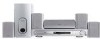
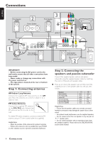
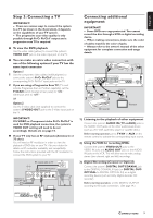
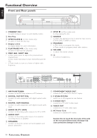
Connections English IMPORTANT! - Before connecting the AC power cord to the wall outlet, ensure that all other connections have been made. - Never make or change any connections with the power switched on. - The type plate is located at the rear or bottom of the system. Step 1: Connecting antennas AM Indoor Loop Antenna Connect the supplied AM loop antenna to the AM jack. Place the antenna on a shelf or attach it to a stand or wall. FM Indoor Antenna Connect the supplied FM antenna to the FM (75Ω) jack. Extend the FM antenna and fix its ends to the wall. For better FM stereo reception, connect an external FM antenna using an 75 ohm coaxial cable (not supplied.) Helpful Hints: - Adjust the position of the antennas for optimal reception. - Position the antennas as far as possible from your TV,VCR or other radiation source to prevent unwanted interference. Step 2: Connecting the speakers and passive subwoofer Connect the supplied speaker systems and passive subwoofer using the supplied speaker cables by matching the colors of the jacks and speaker cables. G Press up (or down) the speaker's jack and fully insert the stripped portion of the speaker cable into the jack, then release. Speakers Front Left (FL) Front Right (FR) Center (C) Surround Left (SL) Surround Right (SR) Subwoofer (SUBW) - black black black black black black + white red green blue gray purple Helpful Hints: - Ensure that the speaker cables are correctly connected. Improper connections may damage the system due to shortcircuit. - For optimal sound performance, use the supplied speakers. - Do not connect more than one speaker to any one pair of +/- speaker jacks. - Do not connect speakers with an impedance lower than the speakers supplied. Please refer to the SPECIFICATIONS section of this manual. 8 CONNECTIONS
-
 1
1 -
2
-
3
-
4
-
 5
5 -
 6
6 -
 7
7 -
 8
8 -
 9
9 -
 10
10 -
 11
11 -
 12
12 -
 13
13 -
 14
14 -
 15
15 -
16
-
17
-
18
-
19
-
20
-
21
-
22
-
23
-
24
-
25
-
26
-
27
-
28
-
29
 |
 |
