Magnavox MRD210 User Manual - Page 11
Step 3: Connecting a TV, Connecting additional, equipment - progressive scan dvd
 |
UPC - 037849935385
View all Magnavox MRD210 manuals
Add to My Manuals
Save this manual to your list of manuals |
Page 11 highlights
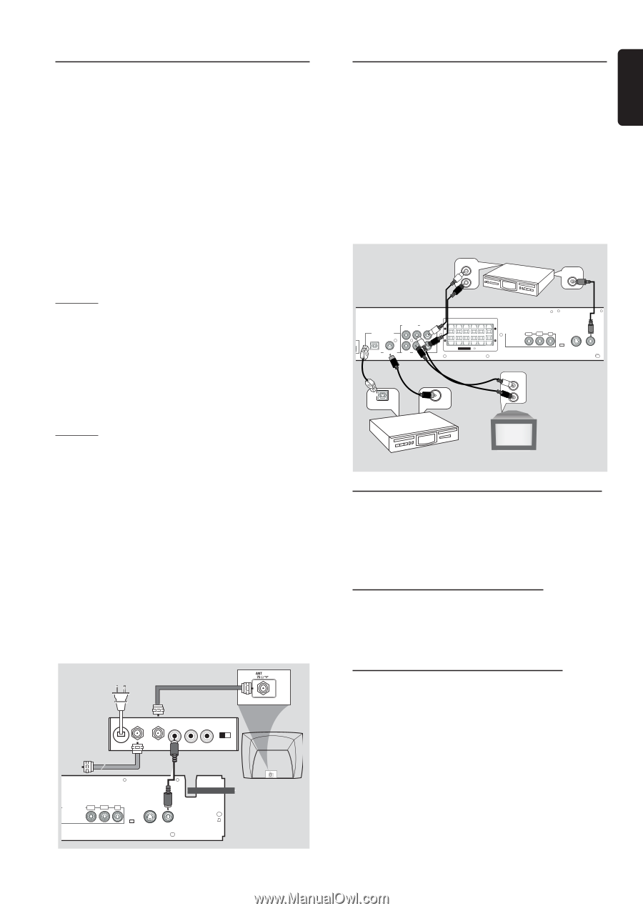
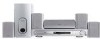
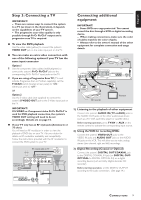
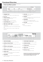
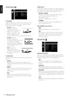
English Step 3: Connecting a TV IMPORTANT! - There are various ways to connect the system to a TV (as shown in the illustration), it depends on the capabilities of your TV system. - The progressive scan video quality is only possible through Pr/Cr Pb/Cb Y output and a progressive scan TV is required. G To view the DVD playback Use the video cable (yellow) to connect the system's VIDEO OUT jack to the video input jack on the TV. G You can make an extra video connection with one of the following options if your TV has the same input connector Option 1 1 Use the component video cables (red/blue/green) to connect the system's Pr/Cr Pb/Cb Y jacks to the corresponding Pr/Cr Pb/Cb Y input jacks on the TV. 2 If you are using a Progressive Scan TV (TV must indicate Progressive Scan or ProScan capability), set the P-SCAN switch (located at rear panel) to "ON." Otherwise, set it to "OFF." OR Option 2 Use the S-video cable (not supplied) to connect the system's S-VIDEO OUT jack to the S-Video input jack on the TV. IMPORTANT! If S-VIDEO or Component video Pr/Cr Pb/Cb Y is used for DVD playback connection, the system's VIDEO OUT setting will need to be set accordingly. Details are on page 14. G If your TV only has an RF-style jack (Antenna In or 75 ohm) You will need an RF modulator in order to view the playback of DVD dics on your TV. Ask your dealer for details on RF modulator availability and compatibility. Follow the instructions provided with the RF modulator to connect the DVD system to your TV. RF coaxial cable to TV Antenna or Cable TV signal INT IN Back of RF Modulator (example only) TO TV VIDEO AUDIO IN IN R L CH3 CH4 SPEAKERS COMPONENT VIDEO OUT Pr/Cr Pb/Cb Y P-SCAN OFF ON S-VIDEO VIDEO OUT OUT Connecting additional equipment IMPORTANT! - Some DVDs are copy-protected. You cannot record the disc through a VCR or digital recording device. - When making connections, make sure the color of cables matches the color of jacks. - Always refer to the owner's manual of the other equipment for complete connection and usage details. AUDIO IN 2L R VCR VIDEO IN 2 DIGITAL OUT AUDIO IN AUDIO OUT L FR FL C SR SL SUBW + + R OPTICAL COAXIAL AUX TV SSPPEEAAKKEERRSS (8 ) COMPONENT VIDEO OUT Pr/Cr Pb/Cb Y P-SCAN OFF ON S-VIDEO VIDEO OUT OUT 3 OPTICAL IN DIGITAL IN 3 CD recorder AUDIO OUT L 1 R Television 1) Listening to the playback of other equipment Connect the system's AUDIO IN (TV or AUX) jacks to the AUDIO OUT jacks on the other audio/visual device (such as a TV, VCR, Laser Disc player or cassette deck.) Before starting operation, press TV/AV or AUX on the remote control to activate the corresponding input source. 2) Using the VCR for recording DVDs Connect the system's VIDEO OUT jacks to the VIDEO IN jacks and AUDIO OUT jacks to the AUDIO IN jacks on the VCR. This will allow you to make analog stereo (two channel, right and left) recordings. 3) Digital Recording (Coaxial or Optical) Connect the system's DIGITAL OUT-COAXIAL jack to the DIGITAL COAXIAL IN jack (or DIGITAL OUTOPTICAL to DIGITAL OPTICAL IN) on a digital recording device (such as Dolby Digital decoder, CD recorder). Before starting operation, set the DIGITAL OUTPUT according to the audio connection. (See page 14.) CONNECTIONS 9
-
 1
1 -
2
-
3
-
4
-
5
-
 6
6 -
 7
7 -
 8
8 -
 9
9 -
 10
10 -
 11
11 -
 12
12 -
 13
13 -
 14
14 -
 15
15 -
 16
16 -
17
-
18
-
19
-
20
-
21
-
22
-
23
-
24
-
25
-
26
-
27
-
28
-
29
 |
 |