Makita LS1016 Technical Reference - Page 10
] Disassembly/assembly
 |
View all Makita LS1016 manuals
Add to My Manuals
Save this manual to your list of manuals |
Page 10 highlights
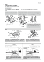
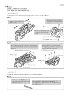
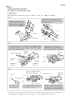
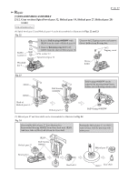
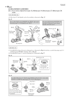
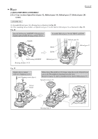
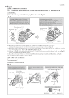
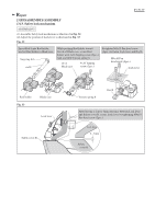
Repair [3] DISASSEMBLY/ASSEMBLY [3]-1. Blade case, Motor section (cont.) ASSEMBLING (4) When assembling Motor section to Blade case, do as illustrated in Fig. 19. Fig. 19 P 10/ 37 Handle rib of Blade case Pressing Handle toward the rib of Blade case, assemble it to Motor housing by tightening with 4x18 Tapping screws. Lead cover Lead cover holder Motor housing 4x18 Tapping screw Pressing Lead cover holder toward Lead cover, assemble it to Handle complete by tightening with 4x18 Tapping screw. [3]-2. Gear section (Spiral bevel gear 32, Helical gear 14, Helical gear 27, Helical gear 28) DISASSEMBLING (1) Lock Blade case at starting position as illustrated in Fig. 8. And remove Link plate as illustrated in Fig. 9. (2) Remove Motor housing and Handle section as illustrated in Figs. 13 and 14. However, no need to remove Handle cover. (3) Tilt Blade case in the direction of Motor housing at 45 degrees to prevent Gear portion from falling off. And then, separate Gear section from Blade case as illustrated in Figs. 20 and 21. Fig. 20 Turn Bearing retainer 14-23 with 1R361 counterclockwise. Bearing retainer can be removed from Blade case. While pressing Shaft lock, remove M5 Hex nut with Socket bit 8. 1R361 Bearing retainer 14-23 M5 Hex nut Spring washer 5 Flat washer 5 M5 Hex nut Fig. 21 Remove the Screws illustrated Insert slotted screwdrivers between Gear section can be separated from below and Bearing retainer 51. Blade case and Bearing box and Blade case together with Bearing box. lift up Bearing box as illustrated M5x16 below. Spiral bevel Pan head screw (3pcs.) shaft of Helical gear 32 Bearing retainer 51 gear 14 Helical gear 27 M5x16 Countersunk head screw (2pcs.) Baring box Helical gear 28
-
 1
1 -
2
-
3
-
4
-
 5
5 -
 6
6 -
 7
7 -
 8
8 -
 9
9 -
 10
10 -
 11
11 -
 12
12 -
 13
13 -
 14
14 -
 15
15 -
16
-
17
-
18
-
19
-
20
-
21
-
22
-
23
-
24
-
25
-
26
-
27
-
28
-
29
-
30
-
31
-
32
-
33
-
34
-
35
-
36
-
37
 |
 |
