Makita LS1016 Technical Reference - Page 9
Figs. 16, and 18, Fig. 16, Fig. 17, Fig. 18, groove, right, Fig. 10
 |
View all Makita LS1016 manuals
Add to My Manuals
Save this manual to your list of manuals |
Page 9 highlights
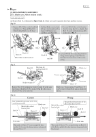
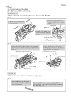
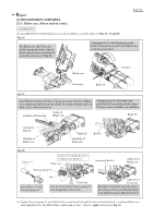
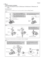
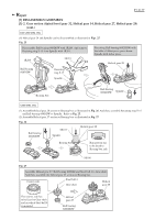
Repair [3] DISASSEMBLY/ASSEMBLY [3]-1. Blade case, Motor section (cont.) P 9/ 37 ASSEMBLING (2) Assemble Rod 16 which functions as an axis for Blade case in the order of Figs. 16 17 and 18. Fig. 16 Put Blade case onto Front arm while aligning the hole to that of Front arm in order to pass Rod 16 smoothly in the step of Fig. 15. Aligning notch C with Stopper pin, push Knob 20 toward the notch to lock Blade case at the lowest position. Blade case notch C Front arm Knob 20 Fig. 17 Insert Rod 16 from the left hole of Front arm to the left hole of Blade case completely until the top end of Rod 16 is flush with the inside of Blade case as illustrated below. left hole of Front arm inside of Blade case Aligning notch A with Stopper pin, push Knob 20 toward the notch to keep 90 degrees between Blade case and Base. Knob 20 top end of Rod 16 left hole of Blade case Knob 20 right hole of Front arm Rod 16 Fig. 18 Sleeve 17 Groove for setting the tail of Compression spring 35 Blade case Torsion spring 35 top end of Rod 16 right hole of Blade case Insert Sleeve 17 into Torsion spring 35. tail Front arm Put one of the tail of Torsion spring 35 into the groove of Front arm. right hole of Front arm Push Rod 16 until the top end reaches the surface of Front arm through Blade case and Front arm as illustrated above. (3) Tighten Torsion spring 35 with M6x20 Hex socket head bolt until the Hex socket head bolt is seated on Blade case. And tighten Rod 16 with M6x16 Hex socket head set bolt. Refer to right illustration in Fig. 10.
-
 1
1 -
2
-
3
-
 4
4 -
 5
5 -
 6
6 -
 7
7 -
 8
8 -
 9
9 -
 10
10 -
 11
11 -
 12
12 -
 13
13 -
 14
14 -
15
-
16
-
17
-
18
-
19
-
20
-
21
-
22
-
23
-
24
-
25
-
26
-
27
-
28
-
29
-
30
-
31
-
32
-
33
-
34
-
35
-
36
-
37
 |
 |
