Makita LS1016 Technical Reference - Page 11
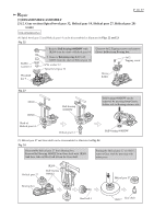
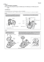
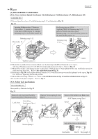
epair, 3] DISASSEMBLY/ASSEMBLY, 3]-2. Gear Spiral bevel gear 32, Helical gear 14, Helical
 |
View all Makita LS1016 manuals
Add to My Manuals
Save this manual to your list of manuals |
Page 11 highlights
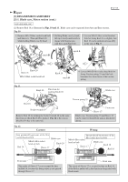
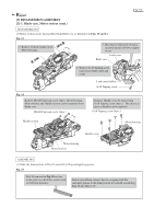
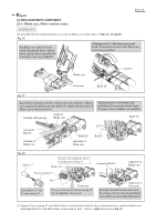
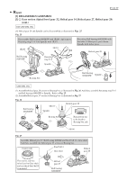
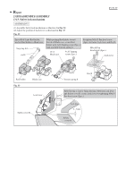
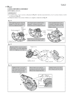
P 11/ 37 Repair [3] DISASSEMBLY/ASSEMBLY [3]-2. Gear section (Spiral bevel gear 32, Helical gear 14, Helical gear 27, Helical gear 28) (cont.) DISASSEMBLING (4) Spiral bevel gear 32 and Helical gear 14 can be disassembled as illustrated in Figs. 22 and 23. Fig. 22 Rubber washer 12 Woodruff key 4 1. Remove Ball bearing 608DDW with 1R269 from the shaft of Helical gear 14. 2. Remove Retaining ring S-12 with 1R291 from the shaft of Helical gear 14. Flat washer 12 Spiral bevel gear 32 Unscrew 4x12 Tapping screws and remove Grease holder from Bearing box. 4x12 Tapping screw Grease holder Fig. 23 1R045 1R346 Ball bearing 608DDW Ball bearing 608DDW can be removed by pressing from Grease holder side to Bearing retainer side. Shaft of Helical gear 14 Helical gear 14 Ball bearing 608DDW (5) Helical gear 27 and Gear shaft can be disassembled as illustrated in Fig. 24. Fig. 24 Disassemble Helical gear 27 from Bearing box. Remove Ball bearing 6000ZZ from Gear shaft with 1R269. And then, take out Steel ball 4 from the Gear shaft. Putting the Helical gear 27 on 1R217, remove Gear shaft by pressing with arbor press. Helical gear 27 1R269 Ball bearing 6000ZZ Bearing box Helical gear 27 Steel ball 4 Gear shaft 1R217
-
 1
1 -
2
-
3
-
4
-
5
-
 6
6 -
 7
7 -
 8
8 -
 9
9 -
 10
10 -
 11
11 -
 12
12 -
 13
13 -
 14
14 -
 15
15 -
 16
16 -
17
-
18
-
19
-
20
-
21
-
22
-
23
-
24
-
25
-
26
-
27
-
28
-
29
-
30
-
31
-
32
-
33
-
34
-
35
-
36
-
37
 |
 |
