Makita LS1016 Technical Reference - Page 18
] DISASSEMBLY/ASSEMBLY, 3]-6. Positive lock mechanism of Turn base, epair
 |
View all Makita LS1016 manuals
Add to My Manuals
Save this manual to your list of manuals |
Page 18 highlights
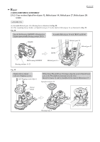
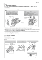
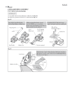
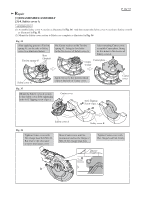
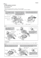
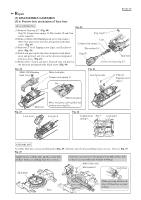
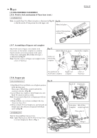
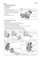
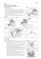
Repair [3] DISASSEMBLY/ASSEMBLY [3]-6. Positive lock mechanism of Turn base P 18/ 37 DISASSEMBLING Fig. 40 (1) Remove Stop ring E-7. (Fig. 40) Grip 50, Compression spring 11, Flat washer 10 and Cam Stop ring E-7 can be removed. (2) Remove M6x14 H.S.Binding head screw then remove Miter lock plate in the direction designated with black arrow. (Fig. 41) Cam Compression spring 11 (3) Remove CT 4x16 Tapping screw (2pcs.) and Lock lever plate. (Fig. 42) Flat washer 10 (4) Push Lock pin 6 in the direction designated with black arrow and pick up Lock lever in the direction designated Grip 50 Turn base with gray arrow. (Fig. 43) (5) Remove Pin 3 from Lock pin 6, then pull out Lock pin 6 in Groove for Stop ring E-7 the direction designated with black arrow. (Fig. 44) Fig. 41 M6x14 H.S.Binding head screw Miter lock plate Compression spring 13 Pin Fig. 42 Lock lever plate CT4x16 Tapping screw (2pcs.) Turn base Fig. 43 Lock lever Miter lock plate Miter lock plate can be pulled out without removing Pin. Lock pin 6 Fig. 44 Compression spring 6 Pin 3 Lock pin 6 ASSEMBLING Assemble Turn base section as illustrated in Fig. 45. And then, take the disassembling step in reverse. Refer to Fig. 37. Fig. 45 Apply Grease to Slide plate and the center hole of Base before assembling Turn base section. Turn base section has to be tightened with M8x45 Hex bolt so that it can smoothly turn without wobbling. M8x45 Hex bolt Flat washer 8 Lock lever Slide plate While pressing down Lock lever, fit Turn base section to Base. Base
-
 1
1 -
2
-
3
-
4
-
5
-
6
-
7
-
8
-
9
-
10
-
11
-
12
-
 13
13 -
 14
14 -
 15
15 -
 16
16 -
 17
17 -
 18
18 -
 19
19 -
 20
20 -
 21
21 -
 22
22 -
 23
23 -
24
-
25
-
26
-
27
-
28
-
29
-
30
-
31
-
32
-
33
-
34
-
35
-
36
-
37
 |
 |
