Makita LS1016 Technical Reference - Page 19
] DISASSEMBLY/ASSEMBLY, 3]-6. Positive lock mechanism of Turn base cont., 3]-7. Assembling
 |
View all Makita LS1016 manuals
Add to My Manuals
Save this manual to your list of manuals |
Page 19 highlights
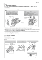
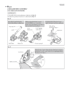
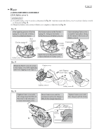
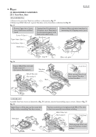
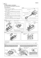
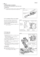
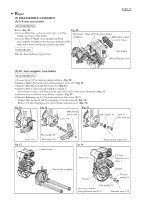
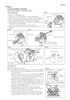
Repair [3] DISASSEMBLY/ASSEMBLY [3]-6. Positive lock mechanism of Turn base (cont.) ASSEMBLING Note: Assemble Grip 50 to Miter lock plate as illustrated in Fig. 46 Fig. 46 so that the notch of Cam portion faces the upper side. Miter lock plate notch of Cam portion of Grip 50 P 19/ 37 [3]-7. Assembling of Square rod complete Match both ends of Square rod complete with the notches of Arm holder complete on condition that the notches are closest position to the center of Turn base, and tighten M5x30 Hex bolt (2pcs.) as illustrated in Fig. 47. Note: Face the concave of Square rod complete to the center of Turn base. Fig. 47 M5x30 Hex bolt (2pcs.) notches of Arm holder complete Arm holder complete threaded holes of Arm holder complete [3]-8. Stopper pin DISASSEMBLING Fig. 48 1) Push Knob 20 to lock Blade case at highest position in the moving range. Then remove M6x20 Hex socket head bolt for securing Link plate. (Fig. 48) 2) Lower Blade case slightly to hold Stopper pin, turn Knob 20 counterclockwise a little. Note: Do not remove Knob 20, or Stopper pin will not be pulled. 3) Remove Blade case section according to the step shown in clause [3]-1. 4) Remove Knob 20 from Stopper pin, and then pull out Stopper pin in the direction designated with black arrow in Fig. 48. ASSEMBLING Take the disassembling step in reverse. Note: Apply Makita grease SG No.00 to O ring 5 that is fit into Stopper pin. Refer to Fig. 1. Square rod complete center of Turn base Knob 20 Stopper pin Link plate M6x20 Hex complete socket head bolt Flat washer 6 Ring 6
-
 1
1 -
2
-
3
-
4
-
5
-
6
-
7
-
8
-
9
-
10
-
11
-
12
-
13
-
 14
14 -
 15
15 -
 16
16 -
 17
17 -
 18
18 -
 19
19 -
 20
20 -
 21
21 -
 22
22 -
 23
23 -
 24
24 -
25
-
26
-
27
-
28
-
29
-
30
-
31
-
32
-
33
-
34
-
35
-
36
-
37
 |
 |
