Makita LS1016 Technical Reference - Page 20
] DISASSEMBLY/ASSEMBLY, 3]-9. Front arm epair, 3]-10. Arm complete, Arm holder
 |
View all Makita LS1016 manuals
Add to My Manuals
Save this manual to your list of manuals |
Page 20 highlights
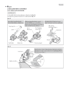
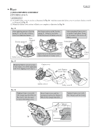
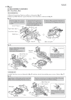
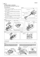
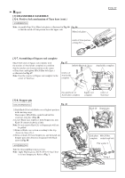
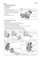
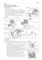
Repair [3] DISASSEMBLY/ASSEMBLY [3]-9. Front arm section P 20/ 37 DISASSEMBLING Refer to Fig. 49. Fig. 49 1) Loosen M6x8 Hex. socket set screw (2pcs.) on Pipe holder and remove Pipe holder. 2) Loosen M6x18 Thumb screw and pull out Front Front arm complete arm complete straightly in the direction designated with white arrow to prevent the pipes from being stuck. Pipes of Front arm complete M6x8 Hex. socket set screw (2pcs.) ASSEMBLING Take the disassembling step in reverse. Pipe holder M6x18 Thumb screw [3]-10. Arm complete, Arm holder DISASSEMBLING 1) Loosen Lever 105 by turning counterclockwise. (Fig. 50) 2) Remove M4x10 Pan head screw and then remove Lever 105. (Fig. 51) 3) Remove M10 Hex bolt and Flat washer 10. (Fig. 51) 4) Remove M10-17 Hex lock nut using Box wrench 17. Flat washer 10 (2pcs.) and Thrust needle cage 1024 can be removed as illustrated in Fig. 52. 5) Remove Arm section from Arm holder complete. (Fig. 53) 6) Remove Retaining ring S-12 from the groove on Arm using 1R291. Stopper, Flat washer 12 and Torsion spring 14 can be removed. (Fig. 54) Remove CT 4x16 Tapping screw (3pcs.) Pointer and Arm cover. (Fig. 54) Fig. 50 Fig. 51 Fig. 52 M4x10 Pan head screw Lever 105 Flat washer 10 M10-17 Hex lock nut Lever 105 Fig. 53 Flat washer 10 M10 Hex bolt Arm section Fig. 54 Arm cover Thrust needle cage 1024 CT 4x16 Tapping screw (3pcs.) Arm holder complete Pointer Stopper Torsion spring 14 Flat washer 12 Groove on Arm for fitting Retainer ring S-12 Retainer ring S-12
-
 1
1 -
2
-
3
-
4
-
5
-
6
-
7
-
8
-
9
-
10
-
11
-
12
-
13
-
14
-
 15
15 -
 16
16 -
 17
17 -
 18
18 -
 19
19 -
 20
20 -
 21
21 -
 22
22 -
 23
23 -
 24
24 -
 25
25 -
26
-
27
-
28
-
29
-
30
-
31
-
32
-
33
-
34
-
35
-
36
-
37
 |
 |
