Makita LS1016 Technical Reference - Page 14
] DISASSEMBLY/ASSEMBLY, 3]-2. Gear Spiral bevel gear 32, Helical gear 14, Helical gear 27,
 |
View all Makita LS1016 manuals
Add to My Manuals
Save this manual to your list of manuals |
Page 14 highlights
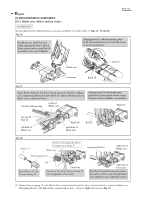
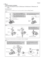
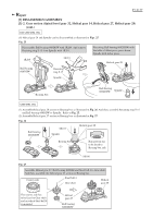
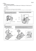
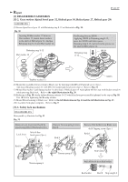
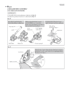
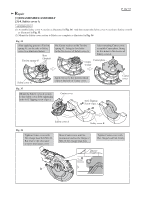
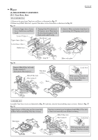
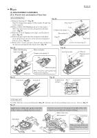
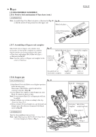
P 14/ 37 Repair [3] DISASSEMBLY/ASSEMBLY [3]-2. Gear section (Spiral bevel gear 32, Helical gear 14, Helical gear 27, Helical gear 28) ASSEMBLING (5) Secure Spiral bevel gear 32 with Retaining ring S-12 as illustrated in Fig. 30. Fig. 30 Inserting Rubber washer 12 between Flat washers 12, mount these washers to the shaft of Helical gear 14. And put Retaining ring S-12 onto Flat washer 12. Retaining ring S-12 Flat washer 12 Put Bearing box on 1R036. Applying 1R028 to Retaining ring S-12, press the 1R028 with Arbor press. Retaining ring S-12 can be fit to the groove on the shaft of Helical gear 14. Retaining ring S-12 1R028 Rubber washer 12 1R036 (6) Mount the assembled Gear section to Blade case by fastening with M5x16 Pan head screw (3pcs.). And fasten Bearing retainer 51 with M5x16 Countersunk head screw (2pcs.). Refer to Fig. 21. (7) Mount Flat washer 5 and Spring washer 5 to the shaft of Helical gear 14. And tighten M5 Hex nut with Socket wrench 8 while pressing Shaft lock. Refer to the right illustration in Fig. 20. (8) Referring to Fig. 20, firmly tighten Bearing retainer 14-23 which has been provisionally tightened in the step in Fig. 28. Use 1R361 for tightening the Bearing retainer. (9) Mount Motor housing to Blade case. Refer to the left illustration in Fig. 14 and the left illustration in Fig. 13. (10) Assemble Link plate complete. Refer to Fig. 9. [3]-3. Safety lock mechanism DISASSEMBLING Disassemble as illustrated in Fig. 31. Fig. 31 Remove Lock lever from Rod 8 by unscrewing M4x10 Pan head screws. M4x10 Pan Lock lever head screw (2pcs.) Remove Torsion spring 8 from Rod 8. Rod 8 Remove Rod holder from Blade case. 4x16 Tapping screw (2pcs.) Rod 8 Rod 8 Torsion spring 8 Rod holder Torsion spring 8 Pull off Rod 8 from Rod holder. Rod holder Rod 8 Stop ring E-6
-
 1
1 -
2
-
3
-
4
-
5
-
6
-
7
-
8
-
 9
9 -
 10
10 -
 11
11 -
 12
12 -
 13
13 -
 14
14 -
 15
15 -
 16
16 -
 17
17 -
 18
18 -
 19
19 -
20
-
21
-
22
-
23
-
24
-
25
-
26
-
27
-
28
-
29
-
30
-
31
-
32
-
33
-
34
-
35
-
36
-
37
 |
 |
