Maytag MFI2266AES Service Manual - Page 10
Service Procedures - filter
 |
View all Maytag MFI2266AES manuals
Add to My Manuals
Save this manual to your list of manuals |
Page 10 highlights
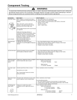
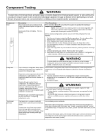
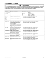
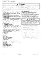
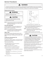
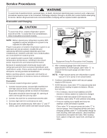
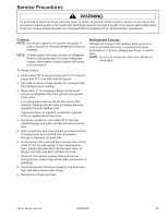
Service Procedures ! WARNING To avoid risk of electrical shock, personal injury, or death, disconnect electrical power source to unit, unless test procedures require power to be connected. Discharge capacitor through a 10,000 ohm resistor before attempting to service. Ensure all ground wires are connected before certifying unit as repaired and/or operational. Service Equipment Listed below is equipment needed for proper servicing of HFC134a systems. Verify equipment is confirmed by manufacturer as being compatible with HFC134a and ester oil system. Equipment must be exclusively used for HFC134a. Exclusive use of equipment only applies to italic items. • Evacuation pump Check with vacuum pump supplier to verify equipment is compatible for HFC134a. Robinair, Model 15600 2 stage, 6 cubic feet per minute pump is recommended. • Four-way manifold gauge set, with low loss hoses • Leak detector • Charging cylinder • Line piercing saddle valve (Schroeder valves). Seals must be HFC134a and ester oil compatible. Line piercing valves may be used for diagnosis but are not suitable for evacuation or charging, due to minute holes pierced in tubing. Do not leave mechanical access valves on system. Valves eventually will leak. Molecules of HFC134a are smaller than other refrigerants and will leak where other refrigerants would not. • Swaging tools • Flaring tools • Tubing cutter • Flux • Sil-Fos • Silver solder • Oil for swaging and flaring Use only part # R0157532 • Copper tubing Use only part # R0174075 and # R0174076 • Dry nitrogen 99.5% minimum purity, with -40°F or lower dew point • Crimp tool • Tube bender • Micron vacuum gauge • Process tube adaptor kit • Heat trap paste • ICI appliance grade HFC134a Drier Replacement Before opening refrigeration system, recover HFC134a refrigerant for safe disposal. Every time sealed HFC134a system is repaired, drier filter must be replaced with, part # B2150504. Cut drier out of system by completing the following steps. Do not unbraze drier filter. Applying heat to remove drier will drive moisture into system. ! WARNING To avoid risk of severe personal injury or death, cut drier at correct location. Cutting drier at incorrect location will allow desiccant beads to scatter. Completely clean area of beads, if spilled. 1. Score capillary tube close to drier and break. 2. Reform inlet tube to drier allowing enough space for large tube cutter. 3. Cut circumference of drier at 1-1/4", below condenser inlet tube joint to drier. 4. Remove drier. 5. Apply heat trap paste on post condenser tubes to protect grommets from high heat. 6. Unbraze remaining part of drier. Remove drier from system. 7. Discard drier in safe place. Do not leave drier with customer. If refrigerator is under warranty, old drier must accompany warranty claim. 10 16026312 ©2006 Maytag Services
-
 1
1 -
2
-
3
-
4
-
 5
5 -
 6
6 -
 7
7 -
 8
8 -
 9
9 -
 10
10 -
 11
11 -
 12
12 -
 13
13 -
 14
14 -
 15
15 -
16
-
17
-
18
-
19
-
20
-
21
-
22
-
23
-
24
-
25
-
26
-
27
-
28
-
29
-
30
-
31
-
32
-
33
-
34
-
35
-
36
-
37
-
38
-
39
-
40
-
41
-
42
-
43
-
44
-
45
-
46
-
47
-
48
-
49
-
50
-
51
-
52
-
53
-
54
-
55
-
56
-
57
-
58
-
59
-
60
-
61
-
62
-
63
-
64
-
65
-
66
-
67
-
68
-
69
-
70
-
71
 |
 |