Maytag MFI2266AES Service Manual - Page 7
Ensure all ground wires are connected before certifying unit as repaired and/or operational. - control board
 |
View all Maytag MFI2266AES manuals
Add to My Manuals
Save this manual to your list of manuals |
Page 7 highlights
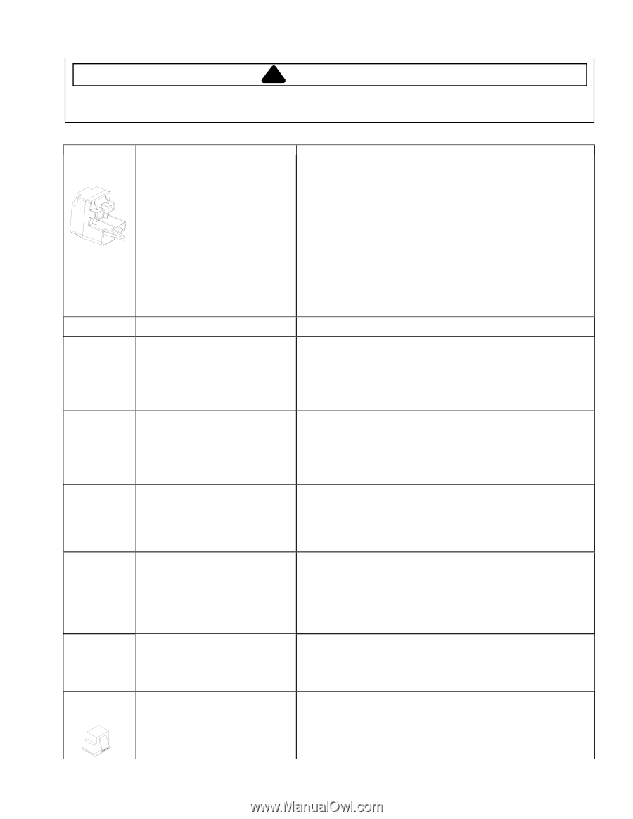
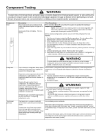
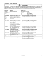
Component Testing ! WARNING To avoid risk of electrical shock, personal injury, or death, disconnect electrical power source to unit, unless test procedures require power to be connected. Discharge capacitor through a resistor before attempting to service. Ensure all ground wires are connected before certifying unit as repaired and/or operational. Component Overload / Relay Description When voltage is connected and relay is cool, current passes through relay to start winding. After a short time, current heats the resistor in relay and resistance will rise blocking current flow through relay. Test Procedures 1. Disconnect power to the refrigerator. 2. Remove relay cover and disconnect leads. 3. Check resistance across terminals 2 and 3 with an ohmmeter: Normal = 3 to 12 ohms Shorted = 0 ohms Open = infinite ohms Start winding remains in the circuit through run capacitor. Control board Evaporator fan motor Solid state relay plugs directly on compressor start and run terminals. Relay terminals 2 and 3 are connected within relay. Run capacitor is connected to relay terminal 3. L2 side of 120 VAC power is connected to relay terminal 2. See "Control Board" section for troubleshooting information. Evaporator fan moves air across 1. Use Control board testing to check operation of motor. evaporator coil and throughout refrigerator 2. If fan motor does not operate, check for voltage at motor leads. cabinet. 3. Replace motor if power is present. 4. Replace Control board if no power. Ice Box fan motor Ice Box fan moves air across Ice Maker and throughout refrigerator cabinet. 1. Use Control board testing to check operation of motor. 2. If fan motor does not operate check for voltage at motor leads. 3. Replace motor if power is present. 4. Replace Control board if no power. Right Refrigerator Single pole, single throw switch completes Check resistant across terminals. & Freezer light circuit for light when door is open. Switch arm depressed switch "C" and "NC" terminals Open Switch arm up "C" and "NC" terminals Closed Ice maker water Controls water flow to the ice maker. valve Controlled by ice maker. Check resistance across coil windings. See "Control Board" section for further testing information. Evaporator heater Activated when defrost thermostat control (defrost) board completes circuit through heater. Left Refrigerator Light Switch Single pole, double throw switch completes circuit for light when door is open. Check resistance across heater. To check defrost system : 1. Use Control Board testing to check operation of defrost heater. 2. If heater does not operate, check defrost thermostat to see if closed. 3. If no power to heater, replace control board. Check resistant across terminals. Switch arm depressed "C" and "NC" terminals Open "C" and "NO" terminals Closed Switch arm up "C" and "NC" terminals Closed "C" and "NO" terminals Open ©2006 Maytag Services 16026312 7
-
 1
1 -
 2
2 -
 3
3 -
 4
4 -
 5
5 -
 6
6 -
 7
7 -
 8
8 -
 9
9 -
 10
10 -
 11
11 -
 12
12 -
13
-
14
-
15
-
16
-
17
-
18
-
19
-
20
-
21
-
22
-
23
-
24
-
25
-
26
-
27
-
28
-
29
-
30
-
31
-
32
-
33
-
34
-
35
-
36
-
37
-
38
-
39
-
40
-
41
-
42
-
43
-
44
-
45
-
46
-
47
-
48
-
49
-
50
-
51
-
52
-
53
-
54
-
55
-
56
-
57
-
58
-
59
-
60
-
61
-
62
-
63
-
64
-
65
-
66
-
67
-
68
-
69
-
70
-
71
 |
 |