Maytag MFI2266AES Service Manual - Page 14
Evacuation and Charging
 |
View all Maytag MFI2266AES manuals
Add to My Manuals
Save this manual to your list of manuals |
Page 14 highlights
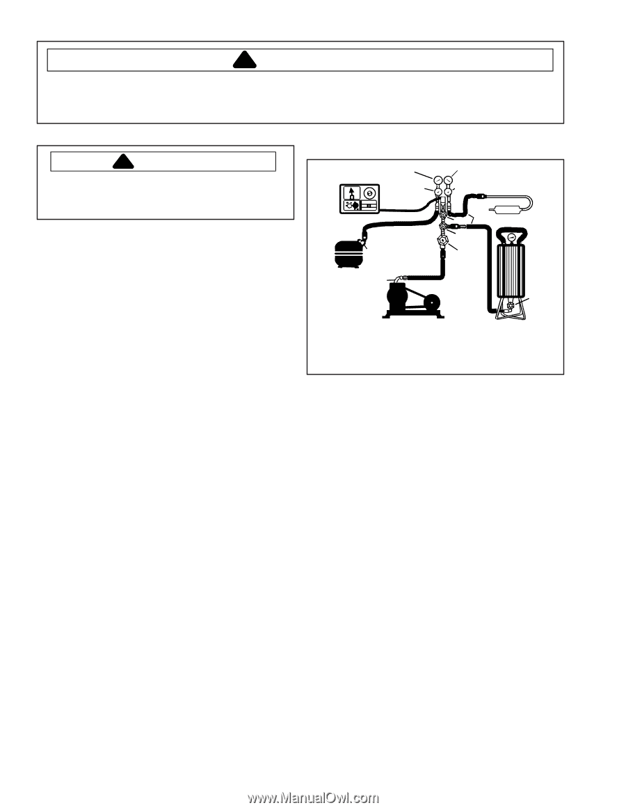
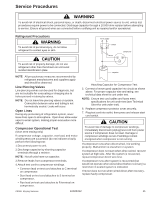
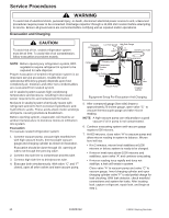
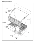
Service Procedures ! WARNING To avoid risk of electrical shock, personal injury, or death, disconnect electrical power source to unit, unless test procedures require power to be connected. Discharge capacitor through a 10,000 ohm resistor before attempting to service. Ensure all ground wires are connected before certifying unit as repaired and/or operational. Evacuation and Charging ! CAUTION To avoid risk of fire, sealed refrigeration system must be air free. To avoid risk of air contamination, follow evacuation procedures exactly. NOTE: Before opening any refrigeration system, EPA regulations require refrigerant in system to be captured for safe disposal. Proper evacuation of sealed refrigeration system is an important service procedure. Usable life and operational efficiency greatly depends upon how completely air, moisture and other non-condensables are evacuated from sealed system. Air in sealed system causes high condensing temperature and pressure, resulting in increased power requirements and reduced performance. Moisture in sealed system chemically reacts with refrigerant and oil to form corrosive hydrofluoric and hydrochloric acids. These acids attack motor windings and parts, causing premature breakdown. Before opening system, evaporator coil must be at ambient temperature to minimize moisture infiltration into system. Evacuation To evacuate sealed refrigeration system: 1. Connect vacuum pump, vacuum tight manifold set with high vacuum hoses, thermocouple vacuum gauge and charging cylinder as shown in illustration. Evacuation should be done through I.D. opening of tubes not through line piercing valve. 2. Connect low side line to compressor process tube. 3. Connect high side line to drier/process tube. 4. Evacuate both simultaneously. With valve "C" and "F" closed, open all other valves and start vacuum pump. Thermistor Vacuum Gauge Low Side Gauge High Side Gauge E Valve D Valve Drier/Process Tube Compressor Charging Hose Compressor Process Tube .6 cm Copper Tubing Vacuum Pump C Charging Hose B A F Valve Charging Cylinder Equipment Setup For Evacuation And Charging 5. After compound gauge (low side) drops to approximately 29 inches gauge, open valve "C" to vacuum thermocouple gauge and take micron reading. NOTE: A high vacuum pump can only produce a good vacuum if oil in pump is not contaminated. 6. Continue evacuating system until vacuum gauge registers 600 microns. 7. At 600 microns, close valve "A" to vacuum pump and allow micron reading in system to balance. Micron level will rise. • If in 2 minutes, micron level stabilizes at 1000 microns or below, system is ready to be charged. • If micron level rises above 1000 microns and stabilizes, open valve "A" and continue evacuating. • If micron reading rises rapidly and does not stabilize, a leak still exists in system. Close valve "A" to vacuum pump and valve "C" to vacuum gauge. Invert charging cylinder and open charging cylinder valve "F" to add partial charge for leak checking. With leak detector, check manifold connections and system for leaks. After locating leak, capture refrigerant, repair leak, and begin at step 1. 14 16026312 ©2006 Maytag Services
-
 1
1 -
2
-
3
-
4
-
5
-
6
-
7
-
8
-
 9
9 -
 10
10 -
 11
11 -
 12
12 -
 13
13 -
 14
14 -
 15
15 -
 16
16 -
 17
17 -
 18
18 -
 19
19 -
20
-
21
-
22
-
23
-
24
-
25
-
26
-
27
-
28
-
29
-
30
-
31
-
32
-
33
-
34
-
35
-
36
-
37
-
38
-
39
-
40
-
41
-
42
-
43
-
44
-
45
-
46
-
47
-
48
-
49
-
50
-
51
-
52
-
53
-
54
-
55
-
56
-
57
-
58
-
59
-
60
-
61
-
62
-
63
-
64
-
65
-
66
-
67
-
68
-
69
-
70
-
71
 |
 |