Maytag MMMF8030PZ Bump Out Kit Installation Instructions - Page 10
Attach Bump Out Mounting Plate to Wall
 |
View all Maytag MMMF8030PZ manuals
Add to My Manuals
Save this manual to your list of manuals |
Page 10 highlights
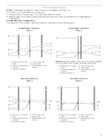
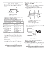
3. Select the right hooks for installation, there are two hooks on the R and P bracket, depends on the cabinet depth, select the right hook before installation. A C B No Wall Studs at End Holes (Figure 1) NOTE: The mounting plate must be secured to the wall on at least 1 wall stud as well as at both ends. 1. With the support hooks of the mounting plate facing forward, insert 3/16-24 x 3" round-head bolts through both end holes (A and B), insert 1/4 x 2" lag screws (D, E, H, and J). . P R P R A. P Hook B. R Hook C. P and R Bracket Cabinet Depth P 15" to 151/2" (38.1 cm to 39.4 cm) R 151/2" to 16" (39.4 cm to 40.6 cm) 4. For example, the cabinet depth is 151/4", choose the P hook, and put the P hooks facing out. A C A H C D E J B A and B. Two End Holes C. Wall Studs D, E, H, and J. Four Lag Screw Holes A. P Hook 5. Fasten P and R bracket with the screws which uninstalled in step 2. NOTE: Start toggle nuts on bolts from the back of the mounting plate. Leave enough space for the toggle nuts to go through the wall and to open. B A C A A. Screws Attach Bump Out Mounting Plate to Wall NOTE: Secure the mounting plate to the wall at both end holes drilled into the wall studs and/or drywall using either 3/16-24 x 3" round-head bolts and toggle nuts and 1/4 x 2" lag screws. Refer to illustrations in "Possible Wall Stud Configurations" in the "Locate Wall Stud(s)" section. Note: If the depth of cabinet is slightly larger than 16", it may be necessary to use a number of the provided spacers, between the mounting plate and the wall, to achieve a more 'Flush' appearance. Stick spacer(s) before position mounting plate on the wall. A. 3/16-24 x 3" round-head bolt B. Mounting plate C. Spring toggle nut 2. Position mounting plate on the wall. 3. Push the 2 bolts with toggle nuts through the drywall, and finger tighten the bolts to make sure toggle nuts have opened against drywall. B Depth of cabinet 13" to 16" 161/16" 161/8" 163/16" 161/4" A. Mounting plate B. 1/16" thickness A Spacer Mounting plate Bump out mounting plate Mounting plate + 4 piece spacer Mounting plate + 8 pieces spacer Mounting plate + 12 piece spacer Mounting plate + 16 pieces spacer A C B D A. 3/16-24 x 3" round-head bolt B. Mounting plate C. Spring toggle nut D. Drywall 10
-
 1
1 -
2
-
3
-
4
-
 5
5 -
 6
6 -
 7
7 -
 8
8 -
 9
9 -
 10
10 -
 11
11 -
 12
12 -
 13
13 -
 14
14 -
 15
15 -
16
-
17
-
18
-
19
-
20
-
21
-
22
-
23
-
24
-
25
-
26
-
27
-
28
-
29
-
30
-
31
-
32
-
33
-
34
-
35
-
36
 |
 |
