Milwaukee Tool Diamond Coring Motor 300/600 RPM 20 Amp with Clutch Operators M - Page 4
Read And Save All Instructions, For Future Use.
 |
View all Milwaukee Tool Diamond Coring Motor 300/600 RPM 20 Amp with Clutch manuals
Add to My Manuals
Save this manual to your list of manuals |
Page 4 highlights
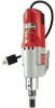
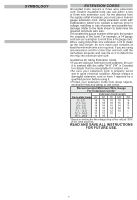
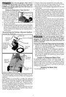
SYMBOLOGY Volts Alternating Current Amps No Load Revolutions per Minute (RPM) C US UL Listing for Canada and U.S. FUNCTIONAL DESCRIPTION 8 2 Shear pin model 1 EXTENSION CORDS Grounded tools require a three wire extension cord. Double insulated tools can use either a two or three wire extension cord. As the distance from the supply outlet increases, you must use a heavier gauge extension cord. Using extension cords with inadequately sized wire causes a serious drop in voltage, resulting in loss of power and possible tool damage. Refer to the table shown to determine the required minimum wire size. The smaller the gauge number of the wire, the greater the capacity of the cord. For example, a 14 gauge cord can carry a higher current than a 16 gauge cord. When using more than one extension cord to make up the total length, be sure each cord contains at least the minimum wire size required. If you are using one extension cord for more than one tool, add the nameplate amperes and use the sum to determine the required minimum wire size. 1. Twist-lock plug 2. Cord 3. Gear shift lever 4. Water shut-off valve 5. Spindle sleeve 6. Retaining ring 7. Shear pin 8. Nameplate 7 Clutch model 6 1 Guidelines for Using Extension Cords • If you are using an extension cord outdoors, be sure 3 it is marked with the suffix "W-A" ("W" in Canada) to indicate that it is acceptable for outdoor use. • Be sure your extension cord is properly wired and in good electrical condition. Always replace a damaged extension cord or have it repaired by a qualified person before using it. • Protect your extension cords from sharp objects, 4 excessive heat and damp or wet areas. Recommended Minimum Wire Gauge For Extension Cords* Extension Cord Length Nameplate Amps 25' 50' 75' 100' 150' 5 6 2 0 - 2.0 2.1 - 3.4 3.5 - 5.0 5.1 - 7.0 7.1 - 12.0 12.1 - 16.0 16.1 - 20.0 18 18 18 18 16 18 18 18 16 14 18 18 16 14 12 18 16 14 12 12 16 14 12 10 -- 14 12 10 -- -- 12 10 -- -- -- * Based on limiting the line voltage drop to five volts at 150% of the rated amperes. READ AND SAVE ALL INSTRUCTIONS FOR FUTURE USE. 3 1. Twist-lock plug 2. Cord 3. Gear shift lever 4. Water shut-off valve 5. Threaded spindle 6. Nameplate 5 4 4
-
 1
1 -
 2
2 -
 3
3 -
 4
4 -
 5
5 -
 6
6 -
 7
7 -
 8
8 -
 9
9 -
 10
10 -
11
-
12
-
13
-
14
-
15
-
16
-
17
-
18
-
19
-
20
-
21
-
22
-
23
-
24
-
25
-
26
-
27
-
28
-
29
-
30
-
31
-
32
-
33
-
34
-
35
-
36
-
37
-
38
-
39
-
40
 |
 |
