NEC NP-PX2201UL User Manual - Page 61
Adjust [RANGE] to determine an area of overlapped edges of images projected from each, projector.
 |
View all NEC NP-PX2201UL manuals
Add to My Manuals
Save this manual to your list of manuals |
Page 61 highlights
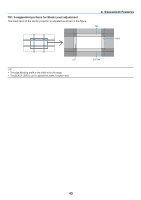
3. Convenient Features ② Adjust [RANGE] to determine an area of overlapped edges of images projected from each projector. When [MARKER] is set to [ON], markers of two colors are displayed on the screen according to the setting of [RANGE]. The red marker represent the edges of the region where images overlap, the green marker represent the range of overlapping (region/width). Turn on [RIGHT] Turn on [LEFT] * The 2 screens are separated in the diagram for explanatory purposes. Adjust the overlapping area (width) with [RANGE]. In the case of the figure on the previous page, adjust the green marker on the left screen onto the red marker on the right screen, and the green marker on the right screen onto the red marker on the left screen. Adjustment is completed when the markers are stacked. Turn off [MARKER] to turn off the marker. TIP: • When displaying a signal with a different resolution, perform the Edge Blending function from the start. • Setting of [MARKER] will not be saved and return to [OFF] when the projector is turned off. • To display or hide the marker while the projector is running, turn on or off [MARKER] from the menu. [BLACK LEVEL] Adjust the brightness of the overlapped section on the screens. According to the necessity, adjust the brightness of the overlapped section on the screens by the [BLACK LEVEL]. • Set the [MODE] to [ON] for selecting [BLACK LEVEL]. 41
-
 1
1 -
2
-
3
-
4
-
5
-
6
-
7
-
8
-
9
-
10
-
11
-
12
-
13
-
14
-
15
-
16
-
17
-
18
-
19
-
20
-
21
-
22
-
23
-
24
-
25
-
26
-
27
-
28
-
29
-
30
-
31
-
32
-
33
-
34
-
35
-
36
-
37
-
38
-
39
-
40
-
41
-
42
-
43
-
44
-
45
-
46
-
47
-
48
-
49
-
50
-
51
-
52
-
53
-
54
-
55
-
 56
56 -
 57
57 -
 58
58 -
 59
59 -
 60
60 -
 61
61 -
 62
62 -
 63
63 -
 64
64 -
 65
65 -
 66
66 -
67
-
68
-
69
-
70
-
71
-
72
-
73
-
74
-
75
-
76
-
77
-
78
-
79
-
80
-
81
-
82
-
83
-
84
-
85
-
86
-
87
-
88
-
89
-
90
-
91
-
92
-
93
-
94
-
95
-
96
-
97
-
98
-
99
-
100
-
101
-
102
-
103
-
104
-
105
-
106
-
107
-
108
-
109
-
110
-
111
-
112
-
113
-
114
 |
 |
