NEC NP-VE281 Users Manual - Page 19
Throw Distance and Screen Size, Distance Chart
 |
View all NEC NP-VE281 manuals
Add to My Manuals
Save this manual to your list of manuals |
Page 19 highlights
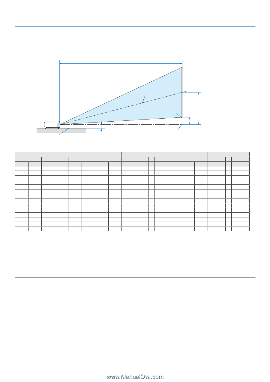
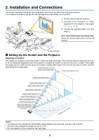
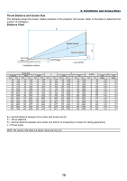
2. Installation and Connections Throw Distance and Screen Size The following shows the proper relative positions of the projector and screen. Refer to the table to determine the position of installation. Distance Chart C Installation surface 2.9"/73 mm Screen center B Screen bottom D Lens center Diagonal inch mm 30 762 40 1016 60 1524 70 1778 80 2032 90 2286 100 2540 120 3048 150 3810 180 4572 200 5080 240 6096 270 6858 300 7620 Screen Size Width inch mm 24 610 32 813 48 1219 56 1422 64 1626 72 1829 80 2032 96 2438 120 3048 144 3658 160 4064 192 4877 216 5486 240 6096 Height inch mm 18 457 24 610 36 914 42 1067 48 1219 54 1372 60 1524 72 1829 90 2286 108 2743 120 3048 144 3658 162 4115 180 4572 B inch 12 16 23 27 31 35 39 47 58 70 78 94 105 117 mm 297 396 594 693 792 891 990 1188 1486 1783 1981 2377 2674 2971 C Wide - inch mm - 46 1180 - 62 1573 - 93 2360 - 108 2753 - 124 3147 - 139 3540 - 155 3933 - 186 4720 - 232 5900 - 279 7080 - 310 7867 - 372 9440 - 418 10620 - 465 11800 - Tele inch mm 52 1320 69 1760 104 2640 121 3080 139 3520 156 3960 173 4400 208 5280 260 6600 312 7920 346 8800 416 10560 468 11880 520 13200 D(WIDE) inch 3 4 5 6 7 8 9 11 13 16 18 22 24 27 mm 69 91 137 160 183 206 228 274 343 411 457 548 617 685 a Wide degree - 14.0 14.0 14.0 14.0 14.0 14.0 14.0 14.0 14.0 14.0 14.0 14.0 14.0 14.0 - Tele degree 12.7 12.7 12.7 12.7 12.7 12.7 12.7 12.7 12.7 12.7 12.7 12.7 12.7 12.7 B = Vertical distance between lens center and screen center C = Throw distance D = Vertical distance between lens center and bottom of screen(top of screen for ceiling application) α = Throw angle NOTE: The values in the tables are design values and may vary. 10
-
 1
1 -
2
-
3
-
4
-
5
-
6
-
7
-
8
-
9
-
10
-
11
-
12
-
13
-
 14
14 -
 15
15 -
 16
16 -
 17
17 -
 18
18 -
 19
19 -
 20
20 -
 21
21 -
 22
22 -
 23
23 -
 24
24 -
25
-
26
-
27
-
28
-
29
-
30
-
31
-
32
-
33
-
34
-
35
-
36
-
37
-
38
-
39
-
40
-
41
-
42
-
43
-
44
-
45
-
46
-
47
-
48
-
49
-
50
-
51
-
52
-
53
-
54
-
55
-
56
-
57
-
58
-
59
-
60
-
61
-
62
-
63
-
64
-
65
-
66
-
67
-
68
-
69
-
70
-
71
-
72
-
73
-
74
-
75
-
76
-
77
-
78
-
79
-
80
-
81
-
82
-
83
-
84
-
85
-
86
-
87
-
88
 |
 |