NEC PX-50XM5A 42XM4/50XM5/61XM4 UM - Page 10
Rear View/ Terminal Board - plasma manual
 |
View all NEC PX-50XM5A manuals
Add to My Manuals
Save this manual to your list of manuals |
Page 10 highlights
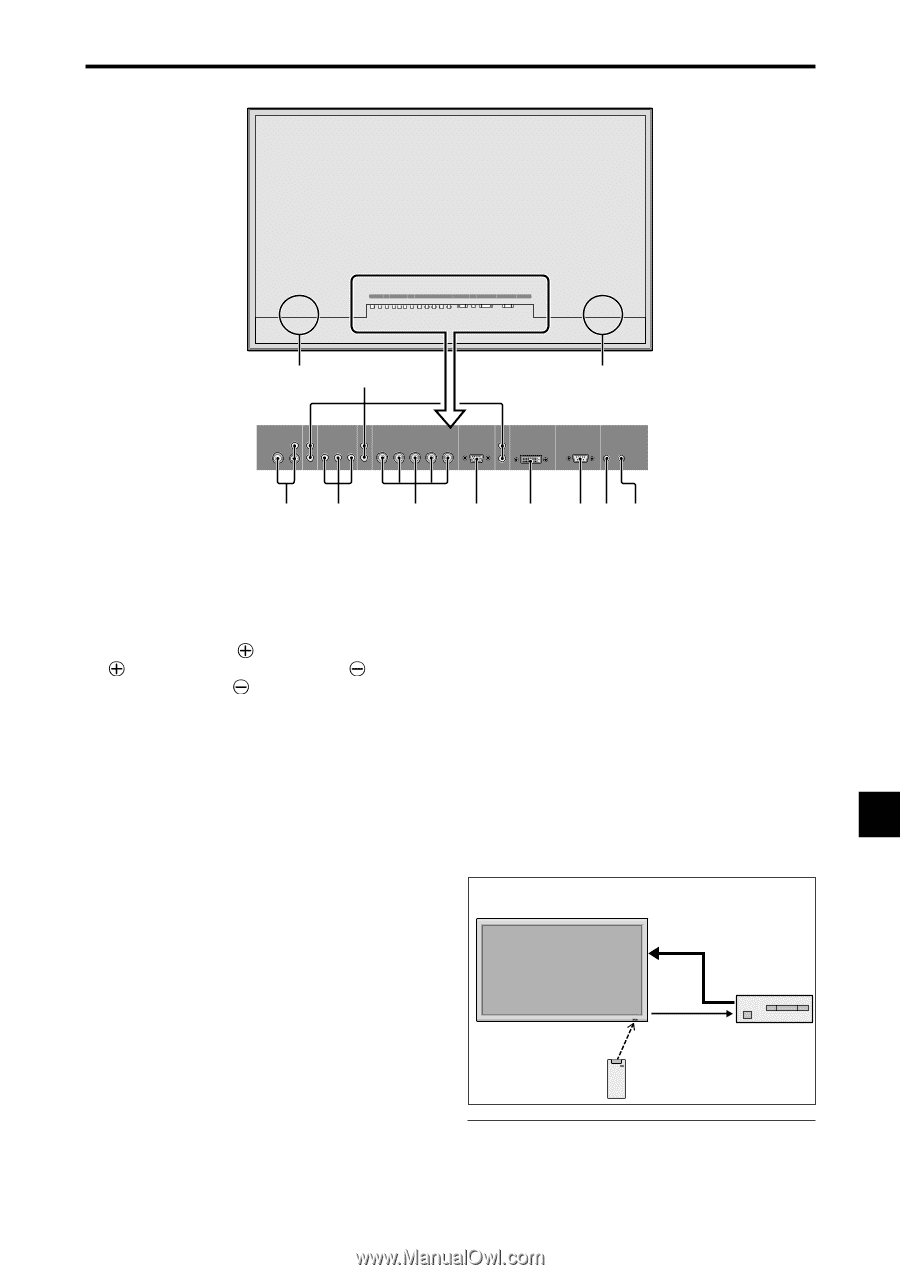
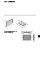
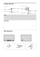
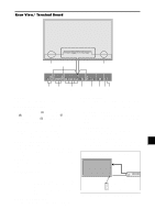
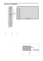
Rear View/ Terminal Board 42 inch VIDEO AUDIO 1 DVD1 / HD1 AUDIO 2 RGB2 / DVD2 / HD2 L/R Y Cb/Pb Cr/Pr L/R R/Cr/Pr G/Y B/Cb/Pb HD VD RGB 1 (IN/OUT) AUDIO 3 L/R RGB 3 DV I EXTERNAL CONTROL REMOTE IN OUT B D A VIDEO 2 AUDIO 1 R DVD1 / HD1 AUDIO 2 R RGB2 / DVD2 / HD2 1(IN/OUT) 3 Y Cb/Pb Cr/Pr R/Cr/Pr G/Y B/Cb/Pb HD VD L (MONO) L (MONO) RGB 1 (IN/OUT) AUDIO 3 R RGB 3 DV I ( Digital RGB ) L (MONO) EXTERNAL CONTROL REMOTE IN OUT CE F G H I JK A AC IN Connect the included power cord here. B EXT SPEAKER L and R Connect speakers (optional) here. Maintain the correct polarity. Connect the (positive) speaker wire to the EXT SPEAKER terminal and the (negative) speaker wire to the EXT SPEAKER terminal on both LEFT and RIGHT channels. Please refer to your speaker's owner's manual. C VIDEO1, 2, 3 (BNC, RCA, S-Video) Connect VCR's, DVD's or Video Cameras, etc. here. VIDEO1 can be used for Input or Output. D AUDIO1, AUDIO2, AUDIO3 These are audio input terminals. The input is selectable. Set which video image corresponds to the audio input from the audio menu screen. E DVD1 / HD1 Connect DVD's, High Definition or Laser Discs, etc. here. F RGB2/ DVD2/ HD2 RGB2: You can connect an analog RGB signal and the syncronization signal. DVD2/ HD2: You can connect DVDs, High Definition sources, Laser Discs, etc. here. This input can be set for use with an RGB or component source. G RGB1 (mini D-Sub 15pin) Connect an analog RGB signal from a computer, etc. here. This input can be used for Input or Output. H RGB3 (DVI 24pin) Connect a digital signal (TMDS) from a source with a DVI output. This input can be set for use with an RGB/PC3. I EXTERNAL CONTROL This terminal is used when operating and controlling the monitor externally with a control system (by RS232C). J REMOTE IN (DC +5V) Connect the remote cable* to the remote control's remote jack to obtain wired remote control. K REMOTE OUT (C-MOS DC +5V) Connect the remote cable* to the REMOTE IN jack of the other display monitor to obtain wired remote control. Connection Example: Connecting a TV tuner PLASMA DISPLAY VIDEO IN REMOTE OUT VIDEO OUT TV Tuner REMOTE IN TV Tuner Remote Control Carrier fHz: 38kHz * The 1/8 Stereo Mini cable must be purchased separately. En-9
-
 1
1 -
2
-
3
-
4
-
 5
5 -
 6
6 -
 7
7 -
 8
8 -
 9
9 -
 10
10 -
 11
11 -
 12
12 -
 13
13 -
 14
14 -
 15
15 -
16
-
17
-
18
-
19
-
20
-
21
-
22
-
23
-
24
-
25
-
26
-
27
-
28
-
29
-
30
-
31
-
32
-
33
-
34
-
35
-
36
-
37
-
38
-
39
-
40
-
41
-
42
-
43
-
44
-
45
-
46
-
47
-
48
-
49
-
50
-
51
-
52
-
53
-
54
-
55
-
56
-
57
-
58
-
59
-
60
-
61
-
62
-
63
-
64
-
65
-
66
-
67
-
68
-
69
-
70
-
71
-
72
-
73
-
74
-
75
-
76
-
77
-
78
-
79
-
80
-
81
-
82
-
83
-
84
-
85
-
86
-
87
-
88
-
89
-
90
-
91
-
92
-
93
-
94
-
95
-
96
-
97
-
98
-
99
-
100
-
101
-
102
-
103
-
104
-
105
-
106
-
107
-
108
-
109
-
110
-
111
-
112
-
113
-
114
-
115
-
116
-
117
-
118
-
119
-
120
-
121
-
122
-
123
-
124
-
125
-
126
-
127
-
128
-
129
-
130
-
131
-
132
-
133
-
134
-
135
-
136
-
137
-
138
-
139
-
140
-
141
-
142
-
143
-
144
-
145
-
146
-
147
-
148
-
149
-
150
-
151
-
152
-
153
-
154
-
155
-
156
-
157
-
158
-
159
-
160
-
161
-
162
-
163
-
164
-
165
-
166
-
167
-
168
-
169
-
170
-
171
-
172
-
173
-
174
-
175
-
176
-
177
-
178
-
179
-
180
-
181
-
182
-
183
-
184
-
185
-
186
-
187
-
188
-
189
-
190
-
191
-
192
 |
 |