NEC PX-50XM5A 42XM4/50XM5/61XM4 UM - Page 24
Option1 Settings Menu
 |
View all NEC PX-50XM5A manuals
Add to My Manuals
Save this manual to your list of manuals |
Page 24 highlights
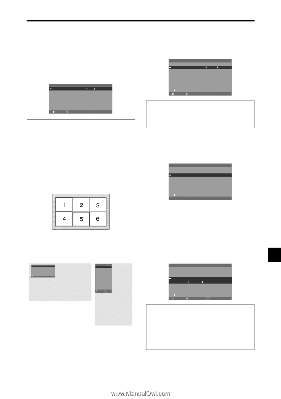
Option1 Settings Menu Setting the on-screen menu This sets the position of the menu, the display format (horizontal or vertical) etc. Example: Turning the DISPLAY OSM off On "OPTION1" menu, select "OSM", then press the MENU/ ENTER button. The "OSM" menu appears. On "DISPLAY OSM" of "OSM" menu, select "OFF". OSM DISPLAY OSM : OSM ADJ. : OSM ANGLE : OSM ORBITER : OSM CONTRAST : OFF 1 H OFF LOW SEL. ADJ. EXIT RETURN Information Ⅵ DISPLAY OSM settings ON: The informations on screen size, volume control, etc. will be shown. OFF: The informations on screen size, volume control, etc. will not be shown. The DISPLAY button on the remote control will not function either. Ⅵ OSM ADJUST settings Adjusts the position of the menu when it appears on the screen. The position can be set between 1 to 6. Ⅵ OSM ANGLE settings Sets the display format (landscape "H" or portrait "V"). When the unit is installed vertically set the OSM ANGLE at "V". "H" "V" OPTION 1 OSM BNC INPUT : RGB D-SUB INPUT : RGB RGB SELECT : AUTO HD SELECT : 1080B INPUT SKIP : OFF ALL RESET : OFF NEXT PAGE SEL. MENU/ENTER OK EXIT RETURN 1 / 4 OPTION1 OSM BNC INPUT : RGB D-SUB INPUT : RGB RGB SELECT : AUTO HD SELECT : 1080B INPUT SKIP : OFF ALL RESET : OFF 1024768 SEL. MENU/ENTER OK EXIT RETURN Ⅵ OSM ORBITER settings ON: The position of the menu will be shifted by eight dots each time OSM is displayed. OFF: OSM will be displayed at the same position. Ⅵ OSM CONTRAST settings NORMAL: OSM brightness is set to normal. LOW: OSM brightness is set to lower. Setting the BNC input connector type Select whether to set the input of the 5 BNC connectors to RGB or Component. Example: Set the BNC INPUT mode to "COMP." On "BNC INPUT" of "OPTION1" menu, select "COMP.". OPTION 1 OSM BNC INPUT : COMP. D-SUB INPUT : RGB RGB SELECT : AUTO HD SELECT : 1080B INPUT SKIP : OFF ALL RESET : OFF NEXT PAGE SEL. ADJ. EXIT RETURN 1 / 4 Information Ⅵ BNC INPUT Settings RGB: Use the 5BNC terminals for RGB input. COMP.: Use the 3BNC terminals for component input. Checking the signal being transmitted to RGB1 terminal Use this to confirm the signal being transmitted to the RGB1 terminal. It is set to RGB and can not be adjusted. OPTION 1 OSM BNC INPUT : RGB D-SUB INPUT : RGB RGB SELECT : AUTO HD SELECT : 1080B INPUT SKIP : OFF ALL RESET : OFF NEXT PAGE CAN NOT ADJUST 1 / 4 Setting a computer image to the correct RGB select screen With the computer image, select the RGB Select mode for a moving image such as (video) mode, wide mode or digital broadcast. Example: Setting the "RGB SELECT" mode to "852ן480 " On "RGB SELECT" of "OPTION1" menu, select "852ן480". OPTION 1 OSM BNC INPUT : RGB D-SUB INPUT : RGB RGB SELECT : 852ן480 HD SELECT : 1080B INPUT SKIP : OFF ALL RESET : OFF NEXT PAGE SEL. ADJ. EXIT RETURN 1 / 4 Information Ⅵ RGB SELECT modes AUTO: Select the suitable mode for the specifications of input signals as listed in the table "Computer input signals supported by this system" on page En-40. The others: The available resolutions are shown. See page En-40 for the details of the above settings. En-23
-
 1
1 -
2
-
3
-
4
-
5
-
6
-
7
-
8
-
9
-
10
-
11
-
12
-
13
-
14
-
15
-
16
-
17
-
18
-
 19
19 -
 20
20 -
 21
21 -
 22
22 -
 23
23 -
 24
24 -
 25
25 -
 26
26 -
 27
27 -
 28
28 -
 29
29 -
30
-
31
-
32
-
33
-
34
-
35
-
36
-
37
-
38
-
39
-
40
-
41
-
42
-
43
-
44
-
45
-
46
-
47
-
48
-
49
-
50
-
51
-
52
-
53
-
54
-
55
-
56
-
57
-
58
-
59
-
60
-
61
-
62
-
63
-
64
-
65
-
66
-
67
-
68
-
69
-
70
-
71
-
72
-
73
-
74
-
75
-
76
-
77
-
78
-
79
-
80
-
81
-
82
-
83
-
84
-
85
-
86
-
87
-
88
-
89
-
90
-
91
-
92
-
93
-
94
-
95
-
96
-
97
-
98
-
99
-
100
-
101
-
102
-
103
-
104
-
105
-
106
-
107
-
108
-
109
-
110
-
111
-
112
-
113
-
114
-
115
-
116
-
117
-
118
-
119
-
120
-
121
-
122
-
123
-
124
-
125
-
126
-
127
-
128
-
129
-
130
-
131
-
132
-
133
-
134
-
135
-
136
-
137
-
138
-
139
-
140
-
141
-
142
-
143
-
144
-
145
-
146
-
147
-
148
-
149
-
150
-
151
-
152
-
153
-
154
-
155
-
156
-
157
-
158
-
159
-
160
-
161
-
162
-
163
-
164
-
165
-
166
-
167
-
168
-
169
-
170
-
171
-
172
-
173
-
174
-
175
-
176
-
177
-
178
-
179
-
180
-
181
-
182
-
183
-
184
-
185
-
186
-
187
-
188
-
189
-
190
-
191
-
192
 |
 |