NEC PX-50XM5A 42XM4/50XM5/61XM4 UM - Page 7
Creating a video wall, Cable Management - remote
 |
View all NEC PX-50XM5A manuals
Add to My Manuals
Save this manual to your list of manuals |
Page 7 highlights
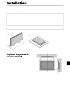
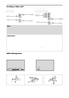
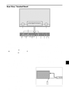
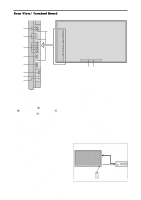
Creating a video wall With built-in matrix display capability, you can create a (2ן2, 3ן3, 4ן4, 5ן5) video wall. • Connect signal cables and remote cables as shown below. Video signal RGB/DVD/HD signal BNC connector R/ Cr/Pr G/ Y RGB2 / DVD2 / HD2 B/ Cb/Pb HD IN VIDEO Signal RCA phono plug VIDEO 3 VIDEO VIDEO 1 ( IN/OUT) VIDEO 2 BNC connector OUT VIDEO Signal RGB signal/ IN DVD/HD signal AUDIO 1 R L (MONO) VD Y DVD1 RGB 1 (IN / OUT) Remote IN control REMOTE OUT IN OUT Remote control Remote IN control IN REMOTE OUT OUT RGB signal/ DVD/HD signal OUT Remote control Note: 1. The VIDEO1 and RGB1 terminals can be used for either INPUT or OUTPUT. When LOOP OUT is ON, do not connect an OUTPUT signal from another unit as it may damage the other unit due to an extraordinary load. 2. LOOP OUT can not be turned ON while signals are input to the RGB1 terminal. 3. LOOP OUT can be turned ON while signals are input to the RGB1 terminal if the POWER is switched ON. Information • To loop signals out to another plasma display, set the LOOP OUT to ON. • To create a video wall, set the VIDEO WALL menu items properly. • To connect monitors, please use a 1~2m (3.3~6.6 feet) BNC cable (any commercially available cable). • If the image quality is poor, do not use the monitor's out terminal. Use a distribution amplifier (any commercially available distribution amplifier) to connect the split signals to the respective monitor INPUT terminals. • Being used as a video wall function, maximaly 4-screen is rough-standard with lower than 1024ן768, 60Hz signal. • A distribution amplifier is particularly recommended when creating a 3ן3 (or greater) video wall. • When looping from plasma to plasma, a 1~2m (3.3~6.6 feet) 15 pin male D-Sub - 5BNC conversion cable is required. Cable Management Using the cable clamps provided with the plasma display; Bundle the signal and audio cables at the back of the unit to connect to the display. 42 inch 50/61 inch Back of the unit Back of the unit mounting holes mounting holes To attach 1. 2. clamp mounting hole To detach cables En-6
-
 1
1 -
 2
2 -
 3
3 -
 4
4 -
 5
5 -
 6
6 -
 7
7 -
 8
8 -
 9
9 -
 10
10 -
 11
11 -
 12
12 -
13
-
14
-
15
-
16
-
17
-
18
-
19
-
20
-
21
-
22
-
23
-
24
-
25
-
26
-
27
-
28
-
29
-
30
-
31
-
32
-
33
-
34
-
35
-
36
-
37
-
38
-
39
-
40
-
41
-
42
-
43
-
44
-
45
-
46
-
47
-
48
-
49
-
50
-
51
-
52
-
53
-
54
-
55
-
56
-
57
-
58
-
59
-
60
-
61
-
62
-
63
-
64
-
65
-
66
-
67
-
68
-
69
-
70
-
71
-
72
-
73
-
74
-
75
-
76
-
77
-
78
-
79
-
80
-
81
-
82
-
83
-
84
-
85
-
86
-
87
-
88
-
89
-
90
-
91
-
92
-
93
-
94
-
95
-
96
-
97
-
98
-
99
-
100
-
101
-
102
-
103
-
104
-
105
-
106
-
107
-
108
-
109
-
110
-
111
-
112
-
113
-
114
-
115
-
116
-
117
-
118
-
119
-
120
-
121
-
122
-
123
-
124
-
125
-
126
-
127
-
128
-
129
-
130
-
131
-
132
-
133
-
134
-
135
-
136
-
137
-
138
-
139
-
140
-
141
-
142
-
143
-
144
-
145
-
146
-
147
-
148
-
149
-
150
-
151
-
152
-
153
-
154
-
155
-
156
-
157
-
158
-
159
-
160
-
161
-
162
-
163
-
164
-
165
-
166
-
167
-
168
-
169
-
170
-
171
-
172
-
173
-
174
-
175
-
176
-
177
-
178
-
179
-
180
-
181
-
182
-
183
-
184
-
185
-
186
-
187
-
188
-
189
-
190
-
191
-
192
 |
 |
