Netgear WBC502 Hardware Installation Guide - Page 15
Bottom panel with Ethernet ports
 |
View all Netgear WBC502 manuals
Add to My Manuals
Save this manual to your list of manuals |
Page 15 highlights
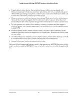
Insight Instant AirBridge WBC502 Hardware Installation Guide Bottom panel with Ethernet ports The following figure shows the bottom panel with the cover removed. 1 3 2 Figure 3. Bottom panel with the cover removed The bottom panel of the AirBridge is covered. When you remove the cover (see Front panel on page 12), the following components display: 1. Reset button. Recessed Reset button (see Reset button on page 18). 2. LAN1 (PoE-24V) port. One 10/100/1000BASE-T RJ-45 PoE port that provides both PoE power and network connectivity to the AirBridge. Using an Ethernet cable, connect the LAN1 port on the AirBridge to the PoE port on the supplied power adapter (see Power adapter on page 16) that is supplied in the package. For an AirBridge that functions as a master in a master-to-satellite setup or as an access point (either in an access point-to-client bridge setup or as standalone access point) at a main site, the network can include wired Internet access. WARNING: Power the AirBridge only with an Ethernet cable that is connected from the LAN1 port to the PoE port on the supplied power adapter. Do not use any other power source such as a PoE switch. The LAN1 port is not a standard PoE port. Using any other power source could damage the device. 3. LAN2 port. One 10/100/1000BASE-T RJ-45 port that allows you to connect an optional single device (such as an IP camera) directly to an AirBridge that functions as a client bridge at a detached site. Hardware Overview 15 Hardware Installation Guide
-
 1
1 -
2
-
3
-
4
-
5
-
6
-
7
-
8
-
9
-
 10
10 -
 11
11 -
 12
12 -
 13
13 -
 14
14 -
 15
15 -
 16
16 -
 17
17 -
 18
18 -
 19
19 -
 20
20 -
21
-
22
-
23
-
24
-
25
-
26
-
27
-
28
-
29
-
30
-
31
-
32
-
33
-
34
-
35
-
36
-
37
-
38
-
39
-
40
-
41
-
42
-
43
-
44
-
45
 |
 |
