Panasonic BB-HCE481A Pro-line Network Cam - Page 165
Caution
 |
UPC - 037988845095
View all Panasonic BB-HCE481A manuals
Add to My Manuals
Save this manual to your list of manuals |
Page 165 highlights
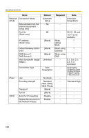
Circuit Diagram Example Camera 12 V Operating Instructions Relay Light 4 3 Door Sensor 2 (Alarm 2) 2 G Door Sensor 1 (Alarm 1) 1 G DC10.5 V-13.5 V CAUTION • The external I/O is not capable of connecting directly to devices that require large amounts of current. In some cases, a custom interface circuit (customer-provided) may have to be used. Serious damage to the camera may result if a device that exceeds its electrical capability is connected to the external I/O (see page 164). • Low voltage/current circuits and high voltage/current circuits are used in the camera circuit. All wiring should be performed by a qualified electrician. Incorrect wiring could damage the camera and cause a fatal electric shock. 165
-
 1
1 -
2
-
3
-
4
-
5
-
6
-
7
-
8
-
9
-
10
-
11
-
12
-
13
-
14
-
15
-
16
-
17
-
18
-
19
-
20
-
21
-
22
-
23
-
24
-
25
-
26
-
27
-
28
-
29
-
30
-
31
-
32
-
33
-
34
-
35
-
36
-
37
-
38
-
39
-
40
-
41
-
42
-
43
-
44
-
45
-
46
-
47
-
48
-
49
-
50
-
51
-
52
-
53
-
54
-
55
-
56
-
57
-
58
-
59
-
60
-
61
-
62
-
63
-
64
-
65
-
66
-
67
-
68
-
69
-
70
-
71
-
72
-
73
-
74
-
75
-
76
-
77
-
78
-
79
-
80
-
81
-
82
-
83
-
84
-
85
-
86
-
87
-
88
-
89
-
90
-
91
-
92
-
93
-
94
-
95
-
96
-
97
-
98
-
99
-
100
-
101
-
102
-
103
-
104
-
105
-
106
-
107
-
108
-
109
-
110
-
111
-
112
-
113
-
114
-
115
-
116
-
117
-
118
-
119
-
120
-
121
-
122
-
123
-
124
-
125
-
126
-
127
-
128
-
129
-
130
-
131
-
132
-
133
-
134
-
135
-
136
-
137
-
138
-
139
-
140
-
141
-
142
-
143
-
144
-
145
-
146
-
147
-
148
-
149
-
150
-
151
-
152
-
153
-
154
-
155
-
156
-
157
-
158
-
159
-
 160
160 -
 161
161 -
 162
162 -
 163
163 -
 164
164 -
 165
165 -
 166
166 -
 167
167 -
 168
168 -
 169
169 -
 170
170 -
171
-
172
-
173
-
174
-
175
-
176
-
177
-
178
-
179
-
180
-
181
-
182
-
183
-
184
-
185
-
186
-
187
-
188
-
189
-
190
-
191
-
192
-
193
-
194
-
195
-
196
-
197
-
198
 |
 |

Operating Instructions
165
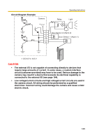
Circuit Diagram Example
CAUTION
•
The external I/O is not capable of connecting directly to devices that
require large amounts of current. In some cases, a custom interface
circuit (customer-provided) may have to be used. Serious damage to the
camera may result if a device that exceeds its electrical capability is
connected to the external I/O (see page 164).
•
Low voltage/current circuits and high voltage/current circuits are used in
the camera circuit. All wiring should be performed by a qualified
electrician. Incorrect wiring could damage the camera and cause a fatal
electric shock.
Light
Door Sensor 1 (Alarm 1)
Door Sensor 2 (Alarm 2)
Relay
Camera
12 V
2
3
4
G
1
G
DC10.5 V–13.5 V